Toyota 4Runner: Illumination for Panel Switch does not Come on with Tail Switch ON
PROCEDURE
|
1. |
CHECK VEHICLE SIGNAL (OPERATION CHECK) |
(a) Enter the "Vehicle Signal Check Mode" screen. Refer to Check Vehicle Signal
in Operation Check (See page .gif) ).
).
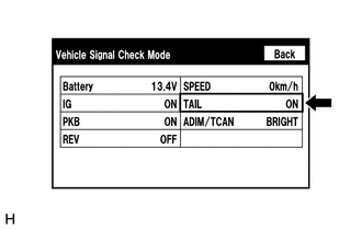
(b) Check that the display changes between ON and OFF according to the light control switch operation.
OK:
|
Light Control Switch |
Display |
|---|---|
|
Tail or head |
ON |
|
Off |
OFF |
HINT:
This display is updated once per second. As a result, it is normal for the display to lag behind the actual switch operation.
| OK | .gif) |
REPLACE RADIO AND DISPLAY RECEIVER ASSEMBLY |
| NG | |
PROCEED TO NEXT SUSPECTED AREA SHOWN IN PROBLEM SYMPTOMS TABLE |
 Radio Broadcast cannot be Received or Poor Reception
PROCEDURE
1.
CHECK RADIO AND DISPLAY RECEIVER ASSEMBLY
(a) Check the radio automatic station search function.
(1) Check the radio automatic station search function b ...
 Display does not Dim when Light Control Switch is Turned ON
PROCEDURE
1.
CHECK IMAGE QUALITY SETTING
(a) Turn the light control switch to the tail or head position.
(b) Check that the daytime screen setting on the display adj ...
Other materials about Toyota 4Runner:
Reassembly
REASSEMBLY
CAUTION / NOTICE / HINT
HINT:
Use the same procedure for the RH and LH sides.
The procedure listed below is for the LH side.
When installing the pad, heat the moulding surface using a heat light.
Standard:
I ...
Door Side Airbag Sensor RH Malfunction (B1690/15,B1695/16)
DESCRIPTION
The side airbag sensor LH or RH consists of the safing sensor, diagnostic circuit,
lateral deceleration sensor, etc.
If the center airbag sensor receives signals from the lateral deceleration sensor,
it determines whether the SRS should be ac ...

0.0278