Toyota 4Runner: Indicator Circuit
DESCRIPTION
The warning indicator lights are installed in the combination meter assembly.
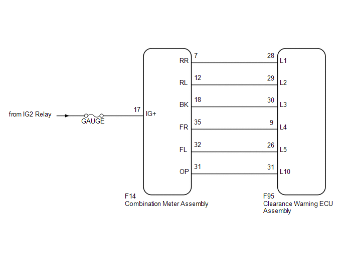
WIRING DIAGRAM
CAUTION / NOTICE / HINT
NOTICE:
Inspect the fuses for circuits related to this system before performing the following inspection procedure.
PROCEDURE
|
1. |
CHECK HARNESS AND CONNECTOR (COMBINATION METER ASSEMBLY - BATTERY) |
|
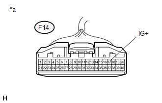
(a) Disconnect the F14 combination meter assembly connector. |
|
(b) Measure the voltage according to the value(s) in the table below.
Standard Voltage:
|
Tester Connection |
Switch Condition |
Specified Condition |
|---|---|---|
|
F14-17 (IG+) - Body ground |
Ignition switch ON |
11 to 14 V |
|
*a |
Front view of wire harness connector (to Combination Meter Assembly) |
| NG | .gif) |
REPAIR OR REPLACE HARNESS OR CONNECTOR |
|
.gif)
|
2. |
CHECK HARNESS AND CONNECTOR (CLEARANCE WARNING ECU ASSEMBLY - COMBINATION METER ASSEMBLY) |
(a) Disconnect the F95 clearance warning ECU assembly connector.
(b) Disconnect the F14 combination meter assembly connector.
(c) Measure the resistance according to the value(s) in the table below.
Standard Resistance:
|
Tester Connection |
Condition |
Specified Condition |
|---|---|---|
|
F95-9 (L4) - F14-35 (FR) |
Always |
Below 1 Ω |
|
F95-26 (L5) - F14-32 (FL) |
Always |
Below 1 Ω |
|
F95-28 (L1) - F14-7 (RR) |
Always |
Below 1 Ω |
|
F95-29 (L2) - F14-12 (RL) |
Always |
Below 1 Ω |
|
F95-30 (L3) - F14-18 (BK) |
Always |
Below 1 Ω |
|
F95-31 (L10) - F14-31 (OP) |
Always |
Below 1 Ω |
|
F95-9 (L4) - Body ground |
Always |
10 kΩ or higher |
|
F95-26 (L5) - Body ground |
Always |
10 kΩ or higher |
|
F95-28 (L1) - Body ground |
Always |
10 kΩ or higher |
|
F95-29 (L2) - Body ground |
Always |
10 kΩ or higher |
|
F95-30 (L3) - Body ground |
Always |
10 kΩ or higher |
|
F95-31 (L10) - Body ground |
Always |
10 kΩ or higher |
| OK | |
PROCEED TO NEXT SUSPECTED AREA SHOWN IN PROBLEM SYMPTOMS TABLE |
| NG | |
REPAIR OR REPLACE HARNESS OR CONNECTOR |
 Clearance Warning Buzzer Circuit
DESCRIPTION
The clearance warning buzzer sounds to alert the driver. The sounding pattern
changes depending on the distance to an obstacle.
WIRING DIAGRAM
PROCEDURE
1.
C ...

Other materials about Toyota 4Runner:
Speed Sensor
Components
COMPONENTS
ILLUSTRATION
Removal
REMOVAL
PROCEDURE
1. REMOVE SPEED SENSOR NT
(a) Disconnect the sensor connector.
(b) Remove the bolt and sensor.
(c) Remove the O-ring from the sensor.
2. REMOVE SPEED SENSOR SP2
(a) Disconnect th ...
Parts Location
PARTS LOCATION
ILLUSTRATION
ILLUSTRATION
ILLUSTRATION
ILLUSTRATION
ILLUSTRATION
...

0.0103