Toyota 4Runner: Inspection
INSPECTION
PROCEDURE
1. INSPECT STEERING PAD SWITCH ASSEMBLY
(a) Inspect the steering pad switch assembly.
(1) Disconnect the switch connector.
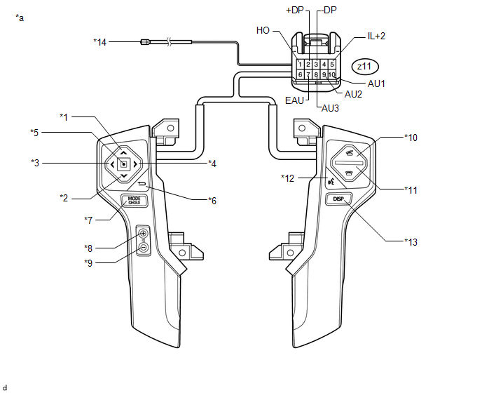 Text in Illustration
|
*1 |
Up Switch |
*2 |
Down Switch |
|
*3 |
Left Switch |
*4 |
Right Switch |
|
*5 |
Enter Switch |
*6 |
Back Switch |
|
*7 |
MODE Switch |
*8 |
Volume+ Switch |
|
*9 |
Volume- Switch |
*10 |
Off Hook (During Dialing or Communication) |
|
*11 |
On Hook (Hong UP the Phone) |
*12 |
Voice Switch |
|
*13 |
DISP Switch |
*14 |
Terminal B |
|
*a |
Component without harness connected (Steering Pad Switch Assembly) |
- |
- |
(2) Measure the resistance according to the value(s) in the table below.
|
Tester Connection |
Switch Condition |
Specified Condition |
|---|---|---|
|
Z11-1 (HO) - Terminal B |
Always |
Below 2.5 Ω |
|
Z11-10 (AU1) - Z11-7 (EAU) |
No Switch pushed |
95 to 105 kΩ |
|
Z11-9 (AU2) - Z11-7 (EAU) |
No Switch pushed |
95 to 105 kΩ |
|
Z11-8 (AU3) - Z11-7 (EAU) |
No Switch pushed |
95 to 105 kΩ |
|
Z11-10 (AU1) - Z11-7 (EAU) |
Up Switch: pushed |
Below 2.5 Ω |
|
Z11-9 (AU2) - Z11-7 (EAU) |
Up Switch: pushed |
95 to 105 kΩ |
|
Z11-8 (AU3) - Z11-7 (EAU) |
Up Switch: pushed |
95 to 105 kΩ |
|
Z11-10 (AU1) - Z11-7 (EAU) |
Down Switch: pushed |
313 to 345 Ω |
|
Z11-9 (AU2) - Z11-7 (EAU) |
Down Switch: pushed |
95 to 105 kΩ |
|
Z11-8 (AU3) - Z11-7 (EAU) |
Down Switch: pushed |
95 to 105 kΩ |
|
Z11-10 (AU1) - Z11-7 (EAU) |
Right Switch: pushed |
95 to 105 kΩ |
|
Z11-9 (AU2) - Z11-7 (EAU) |
Right Switch: pushed |
95 to 105 kΩ |
|
Z11-8 (AU3) - Z11-7 (EAU) |
Right Switch: pushed |
950 to 1050 Ω |
|
Z11-10 (AU1) - Z11-7 (EAU) |
Left Switch: pushed |
95 to 105 kΩ |
|
Z11-9 (AU2) - Z11-7 (EAU) |
Left Switch: pushed |
95 to 105 kΩ |
|
Z11-8 (AU3) - Z11-7 (EAU) |
Left Switch: pushed |
2955 to 3265 Ω |
|
Z11-10 (AU1) - Z11-7 (EAU) |
Enter Switch: pushed |
95 to 105 kΩ |
|
Z11-9 (AU2) - Z11-7 (EAU) |
Enter Switch: pushed |
95 to 105 kΩ |
|
Z11-8 (AU3) - Z11-7 (EAU) |
Enter Switch: pushed |
Below 2.5 Ω |
|
Z11-10 (AU1) - Z11-7 (EAU) |
Back Switch: pushed |
95 to 105 kΩ |
|
Z11-9 (AU2) - Z11-7 (EAU) |
Back Switch: pushed |
95 to 105 kΩ |
|
Z11-8 (AU3) - Z11-7 (EAU) |
Back Switch: pushed |
313 to 345 Ω |
|
Z11-10 (AU1) - Z11-7 (EAU) |
MODE Switch: pushed |
95 to 105 kΩ |
|
Z11-9 (AU2) - Z11-7 (EAU) |
MODE Switch: pushed |
Below 2.5 Ω |
|
Z11-8 (AU3) - Z11-7 (EAU) |
MODE Switch: pushed |
95 to 105 kΩ |
|
Z11-10 (AU1) - Z11-7 (EAU) |
Volume+ Switch: pushed |
950 to 1050 Ω |
|
Z11-9 (AU2) - Z11-7 (EAU) |
Volume+ Switch: pushed |
95 to 105 kΩ |
|
Z11-8 (AU3) - Z11-7 (EAU) |
Volume+ Switch: pushed |
95 to 105 kΩ |
|
Z11-10 (AU1) - Z11-7 (EAU) |
Volume- Switch: pushed |
2955 to 3265 Ω |
|
Z11-9 (AU2) - Z11-7 (EAU) |
Volume- Switch: pushed |
95 to 105 kΩ |
|
Z11-8 (AU3) - Z11-7 (EAU) |
Volume- Switch: pushed |
95 to 105 kΩ |
|
Z11-10 (AU1) - Z11-7 (EAU) |
Off Hook Switch: pushed |
95 to 105 kΩ |
|
Z11-9 (AU2) - Z11-7 (EAU) |
Off Hook Switch: pushed |
950 to 1050 Ω |
|
Z11-8 (AU3) - Z11-7 (EAU) |
Off Hook Switch: pushed |
95 to 105 kΩ |
|
Z11-10 (AU1) - Z11-7 (EAU) |
On Hook Switch: pushed |
95 to 105 kΩ |
|
Z11-9 (AU2) - Z11-7 (EAU) |
On Hook Switch: pushed |
313 to 345 Ω |
|
Z11-8 (AU3) - Z11-7 (EAU) |
On Hook Switch: pushed |
95 to 105 kΩ |
|
Z11-10 (AU1) - Z11-7 (EAU) |
Voice Switch: pushed |
95 to 105 kΩ |
|
Z11-9 (AU2) - Z11-7 (EAU) |
Voice Switch: pushed |
2955 to 3265 Ω |
|
Z11-8 (AU3) - Z11-7 (EAU) |
Voice Switch: pushed |
95 to 105 kΩ |
|
Z11-10 (AU1) - Z11-7 (EAU) |
DISP Switch: pushed |
95 to 105 kΩ |
|
Z11-9 (AU2) - Z11-7 (EAU) |
DISP Switch: pushed |
95 to 105 kΩ |
|
Z11-8 (AU3) - Z11-7 (EAU) |
DISP Switch: pushed |
95 to 105 kΩ |
|
Z11-2 (+DP) - Z11-3 (-DP) |
DISP Switch: pushed |
Below 2.5 Ω |
If the result is not as specified, replace the steering pad switch assembly.
(b) Check the illumination.
(1) Connect the battery positive (+) lead to terminal IL+2 and the negative (-) lead to terminal -DP of the steering pad switch assembly connector.
(2) Check that the switch illumination comes on.
OK:
Steering pad switch illumination comes on.
If the result is not as specified, replace the steering pad switch assembly.
 Removal
REMOVAL
CAUTION / NOTICE / HINT
CAUTION:
Some of these service operations affect the SRS airbag system. Read the precautionary
notices concerning the SRS airbag system before servicing the steeri ...
 Installation
INSTALLATION
PROCEDURE
1. INSTALL STEERING WHEEL ASSEMBLY
(a) Align the matchmarks on the steering wheel assembly and steering main shaft
assembly.
(b) Install the steering wheel assembly set nu ...
Other materials about Toyota 4Runner:
Rear Occupant Classification Sensor RH Circuit Malfunction (B1783)
DESCRIPTION
The rear occupant classification sensor RH circuit consists of the occupant classification
ECU and rear occupant classification sensor RH.
DTC B1783 is stored when a malfunction is detected in the rear occupant classification
sensor RH circui ...
On-vehicle Inspection
ON-VEHICLE INSPECTION
PROCEDURE
1. INSPECT REFRIGERANT PRESSURE WITH MANIFOLD GAUGE SET
(a) This method uses a manifold gauge set to locate problem areas. Read the manifold
gauge pressure when these conditions are established.
Test conditions:
Te ...

0.027