Toyota 4Runner: Rear Power Outlet Socket
Components
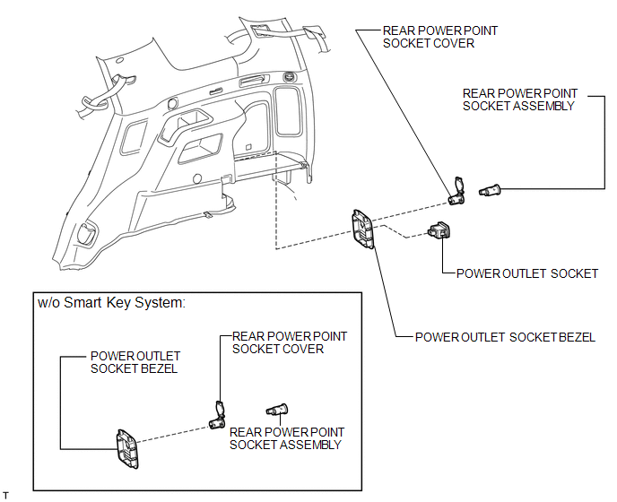
COMPONENTS
ILLUSTRATION
Removal
REMOVAL
PROCEDURE
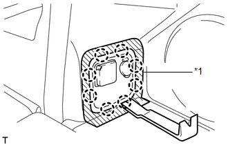
1. REMOVE POWER OUTLET SOCKET BEZEL (w/o Smart Key System)
|
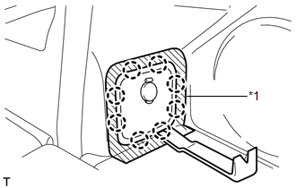
(a) Put protective tape around the power outlet socket bezel. Text in Illustration
|
|
(b) Using a moulding remover, detach the 8 claws and remove the bezel.
|
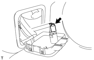
(c) Disconnect the connector. |
|
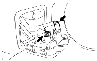
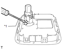
2. REMOVE REAR POWER POINT SOCKET ASSEMBLY (w/o Smart Key System)
|
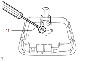
(a) Using a screwdriver, detach the claw and remove the power point socket. HINT: Tape the screwdriver tip before use. Text in Illustration
|
|
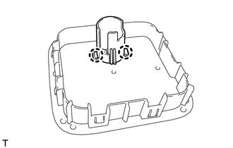
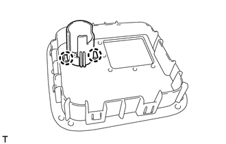
3. REMOVE REAR POWER POINT SOCKET COVER (w/o Smart Key System)
|
(a) Detach the 2 claws and remove the socket cover. |
|
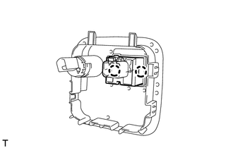
4. REMOVE POWER OUTLET SOCKET BEZEL (w/ Smart Key System)
|
(a) Put protective tape around the power outlet socket bezel. Text in Illustration
|
|
(b) Using a moulding remover, detach the 8 claws and remove the bezel.
|
(c) Disconnect the 2 connectors. |
|
5. REMOVE POWER OUTLET SOCKET (w/ Smart Key System)
|
(a) Detach the 2 claws and remove the socket. |
|
6. REMOVE REAR POWER POINT SOCKET ASSEMBLY (w/ Smart Key System)
|
(a) Using a screwdriver, detach the claw and remove the power point socket. HINT: Tape the screwdriver tip before use. Text in Illustration
|
|
7. REMOVE REAR POWER POINT SOCKET COVER (w/ Smart Key System)
|
(a) Detach the 2 claws and remove the socket cover. |
|
Installation
INSTALLATION
PROCEDURE
1. INSTALL REAR POWER POINT SOCKET COVER (w/o Smart Key System)
(a) Attach the 2 claws to install the socket cover.
2. INSTALL REAR POWER POINT SOCKET ASSEMBLY (w/ Smart Key System)
(a) Attach the claw to install the power point socket.
3. INSTALL POWER OUTLET SOCKET (w/ Smart Key System)
(a) Attach the 2 claws to install the socket.
4. INSTALL POWER OUTLET SOCKET BEZEL (w/ Smart Key System)
(a) Connect the 2 connectors.
(b) Attach the 8 claws to install the bezel.
5. INSTALL REAR POWER POINT SOCKET ASSEMBLY (w/o Smart Key System)
(a) Attach the claw to install the power point socket.
6. INSTALL POWER OUTLET SOCKET BEZEL (w/o Smart Key System)
(a) Connect the connector.
(b) Attach the 8 claws to install the bezel.
7. INSTALL REAR POWER POINT SOCKET COVER (w/ Smart Key System)
(a) Attach the 2 claws to install the socket cover.
 Installation
INSTALLATION
PROCEDURE
1. INSTALL POWER OUTLET SOCKET COVER
(a) Attach the 2 claws to install the socket cover.
2. INSTALL POWER OUTLET SOCKET ASSEMBLY
(a) Attach the claw to install the power ou ...
 Voltage Inverter
...
Other materials about Toyota 4Runner:
Power Window Motor Malfunction (B2311)
DESCRIPTION
The power window regulator motor is operated by the multiplex network master
switch or power window regulator switch. The power window regulator motor assembly
has motor and ECU functions.
This DTC is stored when the power window regulator mo ...
Inspection
INSPECTION
PROCEDURE
1. INSPECT TRANSFER INPUT SHAFT
(a) Using a micrometer, measure the diameter of the input shaft journal.
Minimum diameter:
47.59 mm (1.88 in.)
If the diameter is less than the minimum, replace the input shaft.
(b) Usin ...

0.0248