Toyota 4Runner: Inspection
INSPECTION
CAUTION / NOTICE / HINT
NOTICE:
- The master cylinder and piston are designed so that the piston can easily fall out. Prevent this by making sure the tip of the master cylinder faces downward when handling the master cylinder.
- Make sure foreign matter does not attach to the piston of the master cylinder. If foreign matter attaches, clean it off with a cloth. Then apply lithium soap base glycol grease to the entire outer circumference of the contact surface of the piston.
PROCEDURE
1. INSPECT AND ADJUST BRAKE BOOSTER PUSH ROD
HINT:
Adjust the booster push rod when the master cylinder is replaced with a new one. Adjustment is not necessary when the master cylinder is reinstalled and the booster is replaced with a new one.
(a) Apply chalk to the tip of the accessory tool.
HINT:
An accessory tool is included with a new brake master cylinder sub-assembly.
|
(b) Place the accessory tool on the brake booster assembly. Text in Illustration
|
|
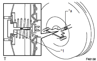
(c) Measure the clearance between the brake booster push rod and accessory tool.
Standard clearance:
0 mm (0 in.)
Adjust the clearance in the following cases:- If there is a clearance between the accessory tool and the shell of the brake booster (floating accessory tool), the push rod is protruding too far.
- If the chalk does not stick on the tip of the brake booster push rod, the push rod protrusion is insufficient.
|
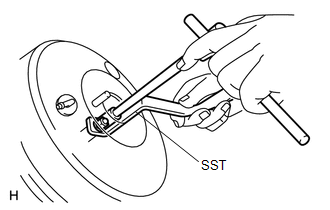
(d) If the clearance is not within the standard, adjust the length by holding the rod using SST and turning the tip of the rod using a 7 mm socket driver. SST: 09737-00020 NOTICE: Check the push rod clearance again after adjusting. |
|
 Removal
REMOVAL
CAUTION / NOTICE / HINT
NOTICE:
Make sure to release the vacuum from the brake booster before removing the master
cylinder from the brake booster.
PROCEDURE
1. DRAIN BRAKE FLUID
NOTICE ...
 Reassembly
REASSEMBLY
PROCEDURE
1. INSTALL MASTER CYLINDER RESERVOIR GROMMET
(a) Apply a light coat of lithium soap base glycol grease to 2 new master cylinder
reservoir grommets.
(b) Install the 2 master ...
Other materials about Toyota 4Runner:
Steering Angle Sensor Internal Circuit (C1433)
DESCRIPTION
Steering angle sensor signals are sent to the skid control ECU via the CAN communication
system. When there is a malfunction in the CAN communication system, it is detected
by the steering angle sensor zero point malfunction diagnostic functio ...
Brake Warning Light Remains ON
DESCRIPTION
The BRAKE warning light comes on when brake fluid is insufficient, the parking
brake is applied or the EBD is defective.
WIRING DIAGRAM
CAUTION / NOTICE / HINT
NOTICE:
When replacing the master cylinder solenoid, perform calibration (See p ...

0.0066