Toyota 4Runner: Inspection
INSPECTION
PROCEDURE
1. INSPECT TRANSFER INPUT SHAFT
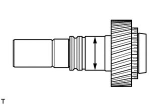
(a) Using a micrometer, measure the diameter of the input shaft journal.
Minimum diameter:
47.59 mm (1.88 in.)
If the diameter is less than the minimum, replace the input shaft.
|
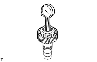
(b) Using a dial indicator, measure the inside diameter of the input shaft bushing. Maximum inside diameter: 39.14 mm (1.54 in.) If the inside diameter is more than the maximum, replace the input shaft. |
|
2. INSPECT PLANETARY PINION GEAR THRUST CLEARANCE
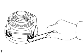
(a) Using a feeler gauge, measure the thrust clearance of the pinion gear.
Standard clearance:
0.11 to 0.84 mm (0.00433 to 0.0331 in.)
Maximum clearance:
0.84 mm (0.0331 in.)
If the clearance is more than the maximum, replace the low planetary gear.
3. INSPECT PLANETARY PINION GEAR RADIAL CLEARANCE
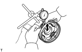
(a) Using a dial indicator, measure the radial clearance of the pinion gear.
Standard clearance:
0.009 to 0.038 mm (0.000354 to 0.00150 in.)
Maximum clearance:
0.038 mm (0.00150 in.)
If the clearance is more than the maximum, replace the low planetary gear.
4. INSPECT TRANSFER DRIVE SPROCKET THRUST CLEARANCE
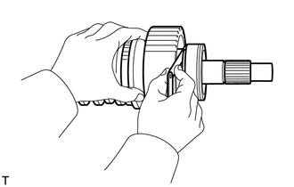
(a) Using a feeler gauge, measure the thrust clearance.
Standard clearance:
0.10 to 0.25 mm (0.00394 to 0.00984 in.)
Maximum clearance:
0.25 mm (0.00984 in.)
If the thrust clearance is more than the maximum, replace the drive sprocket.
5. INSPECT REAR TRANSFER OUTPUT SHAFT
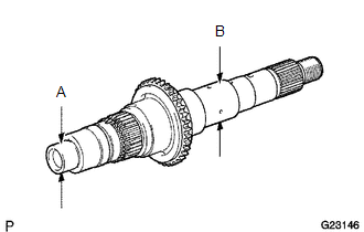
(a) Using a micrometer, measure the diameter of the output shaft journal.
Minimum Diameter:
|
Journal |
Specified Condition |
|---|---|
|
A |
27.98 mm (1.102 in.) |
|
B |
36.98 mm (1.457 in.) |
If the diameter is less than the minimum, replace the output shaft.
6. INSPECT TRANSFER DRIVE SPROCKET RADIAL CLEARANCE
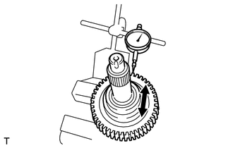
(a) Using a dial indicator, measure the radial clearance between the drive sprocket and output shaft with the needle roller bearing installed.
Standard radial clearance:
0.010 to 0.055 mm (0.000394 to 0.00217 in.)
Maximum radial clearance:
0.055 mm (0.00217 in.)
If the radial clearance is more than the maximum, replace the drive sprocket or needle roller bearing.
7. INSPECT TRANSFER HIGH AND LOW CLUTCH SLEEVE AND NO. 2 TRANSFER GEAR SHIFT FORK CLEARANCE
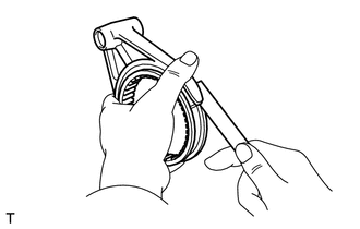
(a) Using a feeler gauge, measure the clearance between the clutch sleeve and No. 2 gear shift fork.
Maximum clearance:
1.0 mm (0.0394 in.)
If the clearance is more than the maximum, replace the clutch sleeve or No. 2 gear shift fork.
8. INSPECT FRONT DRIVE CLUTCH SLEEVE AND NO. 1 TRANSFER GEAR SHIFT FORK CLEARANCE

(a) Using a feeler gauge, measure the clearance between the clutch sleeve and No. 1 gear shift fork.
Maximum clearance:
1.0 mm (0.0394 in.)
If the clearance is more than the maximum, replace the clutch sleeve or No. 1 gear shift fork.
 Disassembly
DISASSEMBLY
PROCEDURE
1. REMOVE TRANSFER INDICATOR SWITCH (4WD POSITION)
2. REMOVE TRANSFER INDICATOR SWITCH (L4 POSITION)
3. REMOVE TRANSFER INDICATOR SWITCH (NEUTRAL POSITION)
4. REMOV ...
 Reassembly
REASSEMBLY
PROCEDURE
1. INSTALL TRANSFER DRIVE SPROCKET SUB-ASSEMBLY
Text in Illustration
*1
Shifting Key
*2
Drive Sprocket
*3
...
Other materials about Toyota 4Runner:
Inspection
INSPECTION
PROCEDURE
1. INSPECT BACK DOOR POWER WINDOW REGULATOR MOTOR ASSEMBLY
(a) Check that the motor gear rotates smoothly as follows.
NOTICE:
Do not apply positive (+) battery voltage to any terminals except terminal
2 (B) to avoid ...
Using the phone book
To enter the menu of each setting, follow the steps below:
• Adding a new phone number 1. “Phonebook” → 2. “Add Entry”
• Setting speed dial 1. “Phonebook” → 2. “Speed Dial (Set speed dial)”
• Changing a registered name 1. “Phon ...
0.0116

