Toyota 4Runner: Disassembly
DISASSEMBLY
PROCEDURE
1. REMOVE TRANSFER INDICATOR SWITCH (4WD POSITION)
.gif)
2. REMOVE TRANSFER INDICATOR SWITCH (L4 POSITION)
3. REMOVE TRANSFER INDICATOR SWITCH (NEUTRAL POSITION)
4. REMOVE TRANSFER CONTROL SHIFT LEVER RETAINER SUB-ASSEMBLY
(a) Remove the 4 bolts and retainer.
5. REMOVE BREATHER OIL DEFLECTOR
(a) Remove the breather oil deflector.
6. REMOVE TRANSFER BEARING RETAINER SUB-ASSEMBLY
(a) Remove the 5 bolts and bearing retainer.
HINT:
If necessary, tap the bearing retainer with a plastic-faced hammer to remove it.
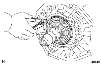
7. REMOVE TRANSFER BEARING RETAINER OIL SEAL
(a) Using a screwdriver and hammer, tap off the oil seal from the bearing retainer.
NOTICE:
Be careful not to damage the oil seal and bearing retainer contact surfaces.
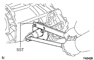
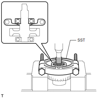
8. REMOVE FRONT OUTPUT SHAFT COMPANION FLANGE SUB-ASSEMBLY
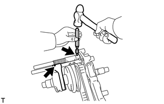
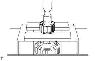
(a) Using a chisel and hammer, loosen the staked part of the lock nut.
|
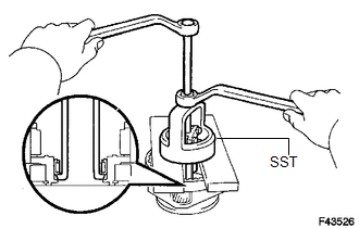
(b) Using SST to hold the companion flange, remove the lock nut. SST: 09330-00021 |
|
|
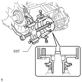
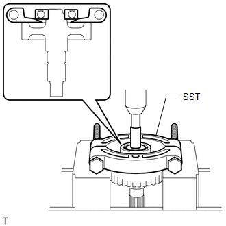
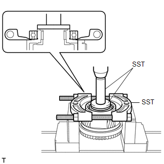
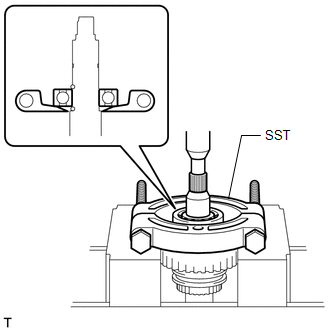
(c) Using SST, remove the companion flange. SST: 09950-40011 09951-04020 09952-04010 09953-04030 09954-04010 09955-04051 09957-04010 09958-04011 |
|
9. REMOVE FRONT TRANSFER OUTPUT SHAFT COMPANION FLANGE OIL SEAL
(a) Using a screwdriver and hammer, tap out the oil seal from the companion flange.
NOTICE:
Be careful not to damage the oil seal and companion flange contact surfaces.
10. REMOVE TRANSFER CASE FRONT OIL SEAL
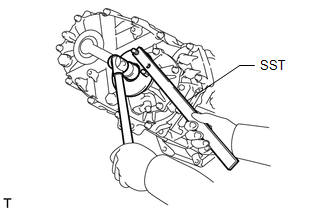
11. REMOVE REAR OUTPUT SHAFT COMPANION FLANGE SUB-ASSEMBLY
(a) Using a chisel and hammer, loosen the staked part of the lock nut.
|
(b) Using SST to hold the companion flange, remove the lock nut. SST: 09330-00021 |
|
|
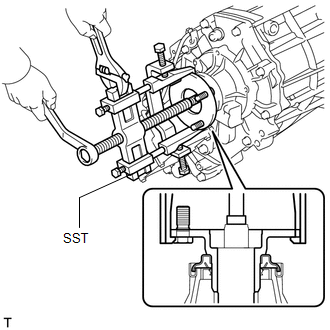
(c) Using SST, remove the companion flange. SST: 09950-40011 09951-04020 09952-04010 09953-04030 09954-04010 09955-04051 09957-04010 09958-04011 |
|
12. REMOVE REAR TRANSFER OUTPUT SHAFT COMPANION FLANGE OIL SEAL
(a) Using a screwdriver and hammer, tap out the oil seal from the companion flange.
NOTICE:
Be careful not to damage the oil seal and companion flange contact surfaces.
13. REMOVE TRANSFER CASE REAR OIL SEAL
14. REMOVE SPEEDOMETER DRIVEN HOLE COVER SUB-ASSEMBLY
(a) Remove the bolt and speedometer driven hole cover sub-assembly.
(b) Remove the O-ring from the hole cover.
15. REMOVE TRANSFER EXTENSION HOUSING SUB-ASSEMBLY
(a) Remove the 5 bolts and extension housing.
HINT:
If necessary, tap the extension housing with a plastic-faced hammer to remove it.
16. REMOVE TRANSFER OUTPUT SHAFT WASHER
(a) Remove the 2 output shaft washers.
17. REMOVE TRANSFER SPEEDOMETER DRIVE GEAR
(a) Remove the speedometer drive gear and ball.
18. REMOVE REAR TRANSFER CASE
(a) Remove the 12 bolts and clamp.
(b) Remove the rear transfer case.
HINT:
If necessary, tap the rear transfer case with a plastic-faced hammer to remove it.
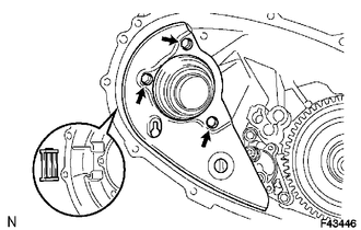
19. REMOVE FRONT TRANSFER DRIVE SHIFT FORK SHAFT
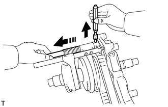
(a) Using a hexagon wrench, remove the 2 plugs.
(b) Using a magnet hand, remove the 2 springs and 2 balls from both holes.
(c) Mount the rear transfer case in a vise.
NOTICE:
Place aluminum plates on the vise to prevent damage to the rear transfer case.
|
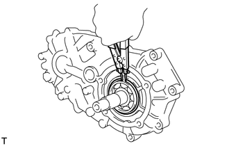
(d) Using a 5 mm pin punch and hammer, tap off the 2 slotted pins from the shift shaft stopper and No. 2 transfer gear shift fork. |
|
|
(e) Hold the shift fork shaft in place by hand when removing the pin punch. |
|
(f) Remove the shift fork shaft, No. 1 gear shift fork, spring and shift shaft stopper.
(g) Using a magnet hand, remove the straight pin.
20. REMOVE TRANSFER HIGH AND LOW SHIFT FORK SHAFT
(a) Remove the shift fork shaft and No. 2 gear shift fork.
21. REMOVE REAR TRANSFER OUTPUT SHAFT, FRONT TRANSFER DRIVE CHAIN AND TRANSFER DRIVEN SPROCKET
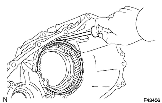
(a) Using a snap ring expander, remove the snap ring.
|
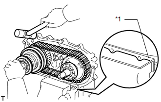
(b) Using a plastic-faced hammer, carefully tap the rear transfer case and remove the output shaft together with the drive chain and driven sprocket. Text in Illustration
|
|
(c) Remove the output shaft and driven sprocket from the drive chain.
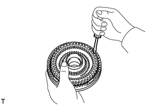
22. REMOVE TRANSFER DRIVEN SPROCKET BEARING
(a) Using SST and a press, press out the bearing.
SST: 09555-55010
NOTICE:
Be careful not to drop or damage the driven sprocket.
23. REMOVE TRANSFER INPUT GEAR RADIAL BALL BEARING
(a) Using SST, a press and steel bar, press out the bearing.
SST: 09555-55010
NOTICE:
Be careful not to drop or damage the driven sprocket.
24. REMOVE FILLER PLUG
(a) Remove the filler plug and gasket.
25. REMOVE DRAIN PLUG
(a) Remove the drain plug and gasket.
26. REMOVE TRANSFER OIL SEPARATOR SUB-ASSEMBLY
(a) Remove the 3 bolts and oil separator.
27. REMOVE TRANSFER CASE MAGNET
28. REMOVE TRANSFER OIL PUMP BODY SUB-ASSEMBLY
(a) Remove the 3 bolts and oil pump body.
29. REMOVE TRANSFER OIL PUMP BODY O-RING
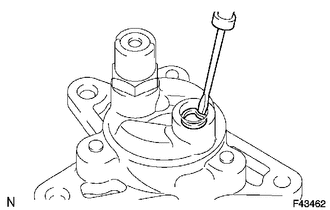
(a) Using a screwdriver, remove the O-ring from the oil pump body.
NOTICE:
Be careful not to damage the oil pump body.
30. REMOVE TRANSFER OIL PUMP GEAR
(a) Remove the oil pump gear.
31. REMOVE TRANSFER LOW PLANETARY GEAR ASSEMBLY WITH TRANSFER INPUT SHAFT
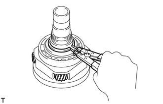
(a) Using a snap ring expander, remove the snap ring.
(b) Remove the low planetary gear together with the input shaft.
32. REMOVE TRANSFER CASE PLUG
(a) Remove the case plug.
33. REMOVE COMPRESSION SPRING
(a) Remove the spring.
34. REMOVE PIN
(a) Remove the pin.
35. REMOVE TRANSFER LOW PLANETARY RING GEAR
(a) Using a screwdriver, pry out the snap ring.
NOTICE:
Be careful not to damage the front transfer case.
(b) Remove the ring gear from the front transfer case.
36. REMOVE TRANSFER CASE OIL SEAL
(a) Using a screwdriver and hammer, tap out the 2 oil seals.
NOTICE:
Be careful not to damage the oil seal and front transfer case contact surfaces.
37. REMOVE TRANSFER LOW PLANETARY GEAR SPLINE PIECE
(a) Using a screwdriver, pry out the snap ring.
NOTICE:
Be careful not to damage the low planetary gear.
(b) Remove the spline piece.
38. REMOVE FRONT TRANSFER OUTPUT SHAFT NEEDLE ROLLER BEARING
(a) Remove the needle roller bearing.
39. REMOVE TRANSFER INPUT GEAR STOPPER SHAFT SNAP RING
(a) Using a snap ring expander, remove the snap ring.
40. REMOVE TRANSFER INPUT GEAR STOPPER
(a) Remove the input gear stopper.
41. REMOVE TRANSFER INPUT GEAR STOPPER BALL
(a) Remove the ball.
42. REMOVE MANUAL TRANSFER PLANETARY CARRIER WASHER
(a) Remove the washer.
43. REMOVE TRANSFER INPUT SHAFT
(a) Remove the input shaft.
44. REMOVE NO. 1 TRANSFER THRUST BEARING RACE
(a) Remove the bearing race.
45. REMOVE TRANSFER LOW PLANETARY GEAR BEARING
(a) Remove the bearing.
46. REMOVE NO. 1 TRANSFER INPUT SHAFT SEAL RING
(a) Remove the 2 seal rings.
47. REMOVE TRANSFER INPUT SHAFT BEARING
(a) Using a snap ring expander, remove the snap ring.
|
(b) Using SST and a press, press out the bearing. SST: 09555-55010 SST: 09950-70010 09951-07150 SST: 09950-60020 09951-00750 NOTICE: Be careful not to drop or damage the low planetary gear. |
|
48. REMOVE TRANSFER LOW PLANETARY GEAR BEARING
(a) Using SST, remove the bearing.
SST: 09612-65014
09612-01030
09612-01050
NOTICE:
Hang SST securely between the bearing and low planetary gear.
49. REMOVE TRANSFER CLUTCH HUB
(a) Using a snap ring expander, remove the snap ring.
(b) Remove the high and low clutch sleeves.
|
(c) Using a press, press out the clutch hub. NOTICE: Be careful not to drop or damage the clutch hub. |
|
50. REMOVE REAR TRANSFER OUTPUT SHAFT RADIAL BALL BEARING
|
(a) Using SST and a press, press out the bearing. SST: 09555-55010 NOTICE: Be careful not to drop or damage the output shaft. |
|
51. REMOVE TRANSFER DRIVE SPROCKET SUB-ASSEMBLY
(a) Remove the spacer and ball.
(b) Remove the drive sprocket with front drive clutch sleeve.
(c) Remove the needle roller bearing.
(d) Remove the front drive synchronizer ring.
(e) Remove the front drive sleeve, 3 shifting keys and 2 shifting key springs from the drive sprocket.
 Removal
REMOVAL
PROCEDURE
1. DRAIN TRANSFER OIL
2. REMOVE AUTOMATIC TRANSMISSION ASSEMBLY
(a) Remove the automatic transmission (See page
).
3. REMOVE TRANSFER ASSEMBLY
(a) Remove the 8 bolts.
(b) ...
 Inspection
INSPECTION
PROCEDURE
1. INSPECT TRANSFER INPUT SHAFT
(a) Using a micrometer, measure the diameter of the input shaft journal.
Minimum diameter:
47.59 mm (1.88 in.)
If the diameter is less tha ...
Other materials about Toyota 4Runner:
Installation
INSTALLATION
CAUTION / NOTICE / HINT
HINT:
Use the same procedure for both the RH and LH sides.
The procedure listed below is for the LH side.
PROCEDURE
1. INSTALL FRONT FENDER MOULDING SUB-ASSEMBLY LH
(a) Install new 9 clips to the fro ...
Windshield wipers and washer
When intermittent windshield wiper operation is selected, the wiper
interval can be adjusted.
The wiper operation is selected by moving the lever as follows.
Type A
1. Intermittent windshield wiper
operation
2. Low speed windshield wiper
operatio ...

0.0064