Toyota 4Runner: Inspection
INSPECTION
PROCEDURE
1. TRANSFER SYSTEM
NOTICE:
- To shift from H2 to H4, move the transfer shift lever while keeping the wheels facing straight ahead.
- To shift from H4 to L4, stop the vehicle, move the shift lever to N and then move the transfer shift lever.
- To shift from L4 to H4, stop the vehicle, move the shift lever to N and then move the transfer shift lever.
2. INSPECT INDICATOR LIGHT
(a) 4WD Indicator Light:
(1) Start the engine.
(2) Move the transfer shift lever from the H2 position to the H4, L4 or N position.
(3) Check that the 4WD indicator light illuminates.
OK:
4WD indicator light comes on or 4WD indicator light comes on after blinking.
If the result is not as specified, inspect the transfer indicator switch (4WD
position) and four wheel drive control ECU. If the system is normal, there may be
a malfunction in the CAN communication system or combination meter. In this case,
first check the CAN communication system (See page
.gif) ). Then check the combination meter (See page
).
). Then check the combination meter (See page
).
(b) 4LO Indicator Light:
(1) Turn the ignition switch to ON.
(2) Move the shift lever to N (vehicle is stopped).
(3) Move the transfer shift lever from the H2, H4 or N position to the L4 position.
(4) Check the 4LO indicator light.
OK:
4LO indicator light comes on or 4LO indicator light comes on after blinking.
If the result is not as specified, inspect the transfer indicator switch (L4
position) and four wheel drive control ECU. If the system is normal, there may be
a malfunction in the CAN communication system or combination meter. In this case,
first check the CAN communication system (See page
). Then check the combination meter (See page
).
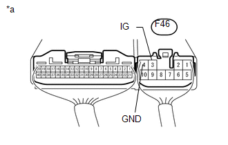
3. INSPECT FOUR WHEEL DRIVE CONTROL ECU (POWER SUPPLY)
|
(a) Measure the voltage according to the value(s) in the table below. Standard voltage:
If the result is not as specified, inspect the fuse, harness or connector.
If the harness or connector is malfunctioning, repair or replace the harness
or connector. If the harness or connector is normal, replace the four wheel
drive control ECU (See page |
|
(b) Measure the resistance according to the value(s) in the table below.
Standard resistance:
|
Tester Connection |
Condition |
Specified Condition |
|---|---|---|
|
A29-4 (GND) - Body ground |
Always |
Below 1 Ω |
If the result is not as specified, repair or replace the harness, fuse or connector.
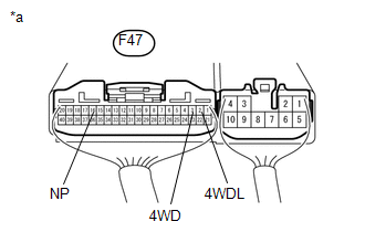
4. INSPECT FOUR WHEEL DRIVE CONTROL ECU (TRANSFER INDICATOR SWITCH)
|
(a) Measure the voltage according to the value(s) in the table below. Standard voltage:
If the result is not as specified, check the power supply. If the power
supply is normal, inspect the transfer indicator switch (See page
|
|
5. CHECK HARNESS AND CONNECTOR (FOUR WHEEL DRIVE CONTROL ECU - TRANSFER INDICATOR SWITCH)
(a) Check the transfer indicator switch (4WD position).
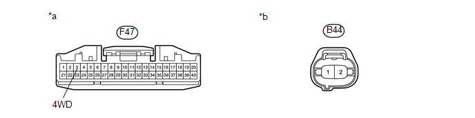
(1) Disconnect the F47 ECU connector.
(2) Disconnect the B44 switch connector.
(3) Measure the resistance according to the value(s) in the table below.
Standard resistance:
|
Tester Connection |
Condition |
Specified Condition |
|---|---|---|
|
F47-3 (4WD) - B44-1 |
Always |
Below 1 Ω |
|
F47-3 (4WD) - Body ground |
Always |
100 kΩ or higher |
|
*a |
Front view of wire harness connector (to Four Wheel Drive Control ECU) |
*b |
Front view of wire harness connector (to Transfer Indicator Switch) |
If the result is not as specified, repair or replace the harness or connector.
(b) Check the transfer indicator switch (L4 position).
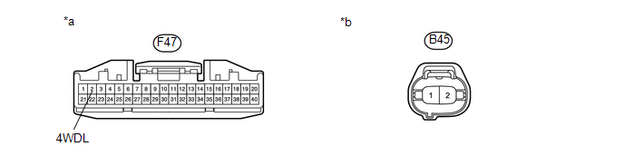
(1) Disconnect the F47 ECU connector.
(2) Disconnect the B45 switch connector.
(3) Measure the resistance according to the value(s) in the table below.
Standard resistance:
|
Tester Connection |
Condition |
Specified Condition |
|---|---|---|
|
F47-2 (4WDL) - B45-1 |
Always |
Below 1 Ω |
|
F47-2 (4WDL) - Body ground |
Always |
100 kΩ or higher |
|
*a |
Front view of wire harness connector (to Four Wheel Drive Control ECU) |
*b |
Front view of wire harness connector (to Transfer Indicator Switch) |
If the result is not as specified, repair or replace the harness or connector.
(c) Check the transfer indicator switch (neutral position).
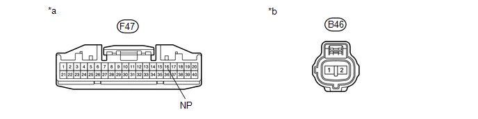
(1) Disconnect the F47 ECU connector.
(2) Disconnect the B46 switch connector.
(3) Measure the resistance according to the value(s) in the table below.
Standard resistance:
|
Tester Connection |
Condition |
Specified Condition |
|---|---|---|
|
F47-16 (NP) - B45-1 |
Always |
Below 1 Ω |
|
F47-16 (NP) - Body ground |
Always |
100 kΩ or higher |
|
*a |
Front view of wire harness connector (to Four Wheel Drive Control ECU) |
*b |
Front view of wire harness connector (to Transfer Indicator Switch) |
If the result is not as specified, repair or replace the harness or connector.
6. INSPECT A.D.D. ACTUATOR
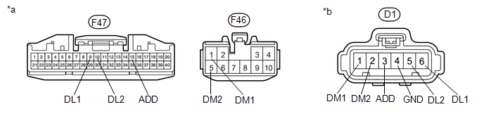
(a) Check the harness and connector (ECU - A.D.D. actuator).
(1) Disconnect the F46 and F47 ECU connectors.
(2) Disconnect the D1 actuator connector.
(3) Measure the resistance according to the value(s) in the table below.
Standard resistance:
|
Tester Connection |
Condition |
Specified Condition |
|---|---|---|
|
F47-9 (DL1) - D1-6 (DL1) |
Always |
Below 1 Ω |
|
F47-9 (DL1) - Body ground |
Always |
100 kΩ or higher |
|
F47-10 (DL2) - D1-5 (DL2) |
Always |
Below 1 Ω |
|
F47-10 (DL2) - Body ground |
Always |
100 kΩ or higher |
|
F47-15 (ADD) - D1-3 (ADD) |
Always |
Below 1 Ω |
|
F47-15 (ADD) - Body ground |
Always |
100 kΩ or higher |
|
F46-1 (DM1) - D1-1 (DM1) |
Always |
Below 1 Ω |
|
F46-1 (DM1) - Body ground |
Always |
100 kΩ or higher |
|
F46-5 (DM2) - D1-2 (DM2) |
Always |
Below 1 Ω |
|
F46-5 (DM2) - Body ground |
Always |
100 kΩ or higher |
|
D1-4 (GND) - Body ground |
Always |
Below 1 Ω |
|
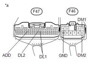
*a |
Front view of wire harness connector (to Four Wheel Drive Control ECU) |
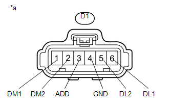
*b |
Front view of wire harness connector (to A.D.D. Actuator) |
If the result is not as specified, repair or replace the harness or connector. If the harness or connector is normal, check the ECU output voltage.
(b) Check the four wheel drive control ECU (A.D.D. actuator).
(1) Connect the F46 and F47 ECU connectors.
(2) Connect the D1 actuator connector.
|
(3) Measure the voltage according to the value(s) in the table below. Standard voltage:
If the result is not as specified, determine if the malfunction is on the ECU side or the actuator side by disconnecting the connector of the A.D.D. actuator, and then checking the ECU output voltage. |
|
(c) Check the four wheel drive control ECU.
(1) Connect the F46 and F47 ECU connectors.
(2) Disconnect the D1 actuator connector.
|
(3) Measure the voltage according to the value(s) in the table below. Standard voltage:
If the result is not as specified, replace the four wheel drive control
ECU (See page |
|
(d) Inspect the A.D.D. actuator (See page ).
 Terminals Of Ecu
TERMINALS OF ECU
1. CHECK 4WD CONTROL ECU
(a) Measure the voltage and resistance according to the value(s) in the table
below.
Terminal No. (Symbol)
Wiring Color
...

Other materials about Toyota 4Runner:
Steering Angle Sensor Communication Stop Mode
DESCRIPTION
Detection Item
Symptom
Trouble Area
Steering Angle Sensor Communication Stop Mode
Either condition is met:
"Spiral cable (Steering Angle Sensor)" is not displayed ...
Precaution
PRECAUTION
1. IGNITION SWITCH EXPRESSION
HINT:
The type of ignition switch used on this model differs according to the specifications
of the vehicle. The expressions listed in the table below are used in this section.
Expression
Ign ...

0.0264