Toyota 4Runner: Terminals Of Ecu
TERMINALS OF ECU
1. CHECK 4WD CONTROL ECU
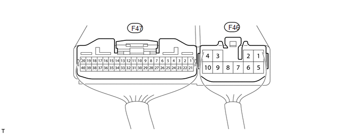
(a) Measure the voltage and resistance according to the value(s) in the table below.
|
Terminal No. (Symbol) |
Wiring Color |
Terminal Description |
Condition |
Specified Condition |
|---|---|---|---|---|
|
F47-2 (4WDL) - F46-4 (GND) |
L - W-B |
Transfer indicator switch (L4 position) |
Ignition switch ON Transfer shift lever position H2 or H4 |
10.5 to 14 V |
|
Ignition switch ON Transfer shift lever position L4 or N |
Below 1.5 V |
|||
|
F47-3 (4WD) - F46-4 (GND) |
B - W-B |
Transfer indicator switch (4WD position) |
Ignition switch ON Transfer shift lever position H2 |
10.5 to 14 V |
|
Ignition switch ON Transfer shift lever position H4, L4 or N |
Below 1.5 V |
|||
|
F47-9 (DL1) - F46-4 (GND) |
LG - W-B |
A.D.D. actuator limit switch |
Ignition switch ON Transfer shift lever position H2 |
Below 1.5 V |
|
Ignition switch ON Transfer shift lever position H4, L4 or N |
10.5 to 14 V |
|||
|
F47-10 (DL2) - F46-4 (GND) |
GR - W-B |
A.D.D. actuator limit switch |
Ignition switch ON Transfer shift lever position H2 |
10.5 to 14 V |
|
Ignition switch ON Transfer shift lever position H4, L4 or N |
Below 1.5 V |
|||
|
F47-15 (ADD) - F46-4 (GND) |
W - W-B |
A.D.D. detection switch |
Ignition switch ON Transfer shift lever position H2 |
9.5 to 14 V |
|
Ignition switch ON Transfer shift lever position H4, L4 or N |
Below 1.5 V |
|||
|
F47-16 (NP) - F46-4 (GND) |
R - W-B |
Transfer indicator switch (Neutral position) |
Ignition switch ON Transfer shift lever position N |
Below 1.5 V |
|
Ignition switch ON Transfer shift lever position not N |
10.5 to 14 V |
|||
|
F47-19 (CANH) - F46-4 (GND) |
G - W-B |
CAN communication line |
Ignition switch ON |
Pulse generation (See waveform 1) |
|
F47-20 (CANL) - F46-4 (GND) |
W - W-B |
CAN communication line |
Ignition switch ON |
Pulse generation (See waveform 2) |
|
F47-21 (L4) - F46-4 (GND) |
R - W-B |
Transfer L4 signal |
Ignition switch ON Transfer shift lever position H2 or H4 |
10 to 14 V |
|
Ignition switch ON Transfer shift lever position L4 or N |
Below 1.5 V |
|||
|
F46-1 (DM1) - F46-4 (GND) |
B - W-B |
A.D.D. actuator motor |
Ignition switch ON Transfer shift lever position H2 → H4, L4 or N (During operation of A.D.D. actuator motor from FREE to LOCK) |
10 to 14 V |
|
Ignition switch ON Transfer shift lever position H2 → H4, L4 or N (A.D.D. actuator motor stopped) |
Below 1.5 V |
|||
|
F46-3 (IG) - F46-4 (GND) |
R - W-B |
IG power |
Ignition switch ON |
11 to 14 V |
|
F46-4 (GND) - Body ground |
W-B - Body ground |
Ground |
Always |
Below 1 Ω |
|
F46-5 (DM2) - F46-4 (GND) |
Y - W-B |
A.D.D. actuator motor |
Ignition switch ON Transfer shift lever position H4, L4 or N → H2 (During operation of A.D.D. actuator motor from LOCK to FREE) |
10 to 14 V |
|
Ignition switch ON Transfer shift lever position H4, L4 or N → H2 (A.D.D. actuator motor stopped) |
Below 1.5 V |
(b) Using an oscilloscope, check waveform 1.
.png) Waveform 1 (Reference)
Waveform 1 (Reference)
|
Item |
Content |
|---|---|
|
Terminal No. (Symbols) |
F47-19 (CANH) - F46-4 (GND) |
|
Tool setting |
1 V/DIV., 10 μsec./DIV. |
|
Condition |
Engine stopped and ignition switch ON |
|
*1 |
Waveform 1 |
HINT:
The waveform varies depending on the CAN communication signal.
(c) Using an oscilloscope, check waveform 2.
.png) Waveform 2 (Reference)
Waveform 2 (Reference)
|
Item |
Content |
|---|---|
|
Terminal No. (Symbols) |
F47-20 (CANL) - F46-4 (GND) |
|
Tool setting |
1 V/DIV., 10 μsec./DIV. |
|
Condition |
Engine stopped and ignition switch ON |
|
*1 |
Waveform 2 |
HINT:
The waveform varies depending on the CAN communication signal.
 Problem Symptoms Table
PROBLEM SYMPTOMS TABLE
HINT:
Use the table below to help determine the cause of problem symptoms.
If multiple suspected areas are listed, the potential causes of the symptoms
are lis ...
 Inspection
INSPECTION
PROCEDURE
1. TRANSFER SYSTEM
NOTICE:
To shift from H2 to H4, move the transfer shift lever while keeping
the wheels facing straight ahead.
To shift from H4 to L4, stop t ...
Other materials about Toyota 4Runner:
Rear Door LH ECU Communication Stop (B2324)
DESCRIPTION
This DTC is stored when LIN communication between the rear power window regulator
motor assembly LH and main body ECU (multiplex network body ECU) stops for 10 seconds
or more.
DTC Code
DTC Detection Condition
...
AUTO LSD system (2WD models)
The AUTO LSD system aids traction by using the traction control system to
control engine performance and braking when one of the rear wheels begins to
spin.
The system should be used only when wheel spinning occurs in a ditch or rough
surface.
System o ...

0.0186