Toyota 4Runner: Installation
INSTALLATION
CAUTION / NOTICE / HINT
HINT:
- Use the same procedure for the RH and LH sides.
- The procedure listed below is for the LH side.
PROCEDURE
1. INSTALL REAR DOOR INSIDE LOCKING CABLE ASSEMBLY LH
.gif)
2. INSTALL REAR DOOR LOCK REMOTE CONTROL CABLE ASSEMBLY LH
3. INSTALL REAR DOOR LOCK ASSEMBLY LH
NOTICE:
- When reusing the removed rear door lock assembly, replace the door lock wiring harness seal on the connector with a new one.
- Do not allow grease or dust to adhere to the surface of the connector which contacts the door lock wiring harness seal.
- Reusing the door lock wiring harness seal or using a damaged door lock wiring harness seal may allow water to enter into the connection. This may result in a malfunction of the rear door lock assembly.
(a) Apply MP grease to the sliding parts of the rear door lock assembly.
(b) Install a new door lock wiring harness seal to the rear door lock assembly.
|
(c) Insert the rear door lock assembly into the rear door outside handle release plate, and set it in place on the rear door panel. |
|
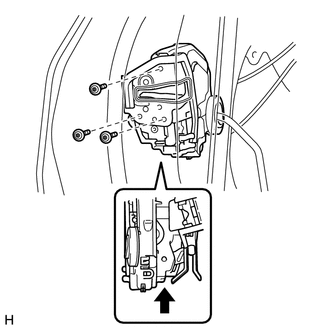
(d) Check that the rear door outside handle frame release plate is securely connected to the rear door lock assembly.
(e) Using a T30 "TORX" wrench, install the rear door lock assembly with the 3 screws.
Torque:
5.0 N·m {51 kgf·cm, 44 in·lbf}
4. INSTALL REAR DOOR GLASS SUB-ASSEMBLY LH
5. INSTALL REAR DOOR QUARTER WINDOW GLASS LH
6. INSTALL REAR DOOR REAR LOWER WINDOW FRAME SUB-ASSEMBLY LH
7. INSTALL REAR DOOR GLASS RUN LH
8. INSTALL REAR DOOR SERVICE HOLE COVER LH
9. INSTALL REAR DOOR INNER GLASS WEATHERSTRIP LH
10. INSTALL REAR DOOR TRIM BOARD SUB-ASSEMBLY LH
11. INSTALL REAR DOOR INSIDE HANDLE BEZEL LH
12. CONNECT CABLE TO NEGATIVE BATTERY TERMINAL
NOTICE:
When disconnecting the cable, some systems need to be initialized after the cable
is reconnected (See page ).
 Inspection
INSPECTION
PROCEDURE
1. INSPECT REAR DOOR LOCK ASSEMBLY LH
(a) Check the door lock motor operation.
(1) Apply battery voltage to the door lock motor and check the operation
of the d ...
 Transmitter Battery(w/ Smart Key System)
Replacement
REPLACEMENT
CAUTION / NOTICE / HINT
NOTICE:
Take extra care when handling these precision electronic components.
PROCEDURE
1. REMOVE TRANSMITTER BATTERY
(a) Push the re ...
Other materials about Toyota 4Runner:
System Diagram
SYSTEM DIAGRAM
Communication Table
Transmitting ECU
Receiving ECU
Signal
Communication Method
Multiplex network master switch assembly
Front power window regulator motor ...
Precaution
PRECAUTION
1. IGNITION SWITCH EXPRESSION
HINT:
The type of ignition switch used on this model differs according to the specifications
of the vehicle. The expressions listed in the table below are used in this section.
Expression
Ign ...

0.008