Toyota 4Runner: Installation
INSTALLATION
CAUTION / NOTICE / HINT
CAUTION:
Wear protective gloves. Sharp areas on the parts may injure your hands.
HINT:
- Use the same procedure for the RH and LH sides.
- The procedure listed below is for the LH side.
PROCEDURE
1. INSTALL REAR NO. 2 SEAT ASSEMBLY LH
(a) Place the rear No. 2 seat assembly in the cabin.
NOTICE:
Be careful not to damage the vehicle body.
HINT:
If installing the seat on the RH side with the LH side installed, install it with the rear seat leg cover LH raised.
(b) Temporarily install the 4 bolts.
(c) Tighten the 4 bolts.
Torque:
37 N·m {377 kgf·cm, 27 ft·lbf}
|
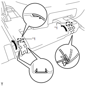
(d) Attach the 6 claws and 2 guides to close the 2 covers. Text in Illustration
|
|
2. INSTALL NO. 1 DECK BOARD BRACKET LH
(a) Install the bracket with the 2 bolts.
3. INSTALL DECK BOARD BRACKET REINFORCEMENT
(a) Attach the 2 hooks to install the reinforcement.
(b) Install the 2 bolts.
4. INSTALL REAR NO. 3 FLOOR BOARD
|
(a) Attach the 2 guides and 4 claws. Text in Illustration
|
|
(b) Attach the clip to install the board.
5. INSTALL REAR NO. 4 FLOOR BOARD
|
(a) Attach the 2 guides and 4 claws. Text in Illustration
|
|
(b) Attach the clip to install the board.
6. INSTALL REAR FLOOR MAT SUPPORT PLATE
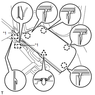
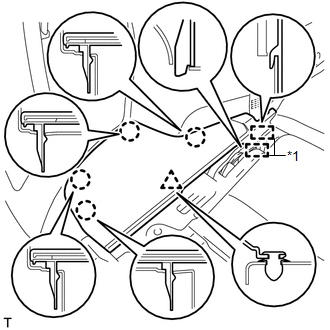
(a) Attach the 5 clips and 2 guides.
(b) Attach the 4 claws to install the plate.
(c) Install the 3 bolts.
7. INSTALL DECK BOARD ASSEMBLY
(a) Attach the 4 clips to install the board.
(b) Install the 2 bolts.
|
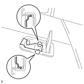
(c) Attach the 2 claws to close the cover. HINT: Use the same procedure to close the cover on the other side. |
|
 Removal
REMOVAL
CAUTION / NOTICE / HINT
CAUTION:
Wear protective gloves. Sharp areas on the parts may injure your hands.
HINT:
Use the same procedure for the RH and LH sides.
The procedure li ...
 Seat Heater Control
Components
COMPONENTS
ILLUSTRATION
Removal
REMOVAL
CAUTION / NOTICE / HINT
CAUTION:
Wear protective gloves. Sharp areas on the parts may injure your hands.
HINT:
Use the same pr ...
Other materials about Toyota 4Runner:
Problem Symptoms Table
PROBLEM SYMPTOMS TABLE
HINT:
Use the table below to help determine the cause of problem symptoms.
If multiple suspected areas are listed, the potential causes of the symptoms
are listed in order of probability in the "Suspected Area" ...
Removal
REMOVAL
CAUTION / NOTICE / HINT
HINT:
Use the same procedure for the RH and LH sides.
The procedure listed below is for the LH side.
PROCEDURE
1. DISCONNECT CABLE FROM NEGATIVE BATTERY TERMINAL
CAUTION:
Wait at least 90 seconds after d ...

0.0232