Toyota 4Runner: Inspection
INSPECTION
PROCEDURE
1. INSPECT REAR DOOR LOCK ASSEMBLY LH
(a) Check the door lock motor operation.
|
(1) Apply battery voltage to the door lock motor and check the operation of the door lock motor. OK:
If the result is not as specified, replace the rear door lock assembly. Text in Illustration
|
|
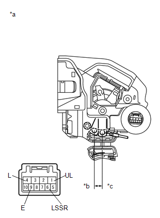
(b) Check the detection switch.
(1) Measure the resistance according to the value(s) in the table below.
Standard Resistance:
|
Tester Connection |
Switch Condition |
Specified Condition |
|---|---|---|
|
6 (LSSR) - 9 (E) |
Lock |
10 kΩ or higher |
|
6 (LSSR) - 9 (E) |
Unlock |
Below 1 Ω |
If the result is not as specified, replace the rear door lock assembly.
2. INSPECT REAR DOOR LOCK ASSEMBLY RH
(a) Check the door lock motor operation.
|
(1) Apply battery voltage to the door lock motor and check the operation of the door lock motor. OK:
If the result is not as specified, replace the rear door lock assembly. Text in Illustration
|
|
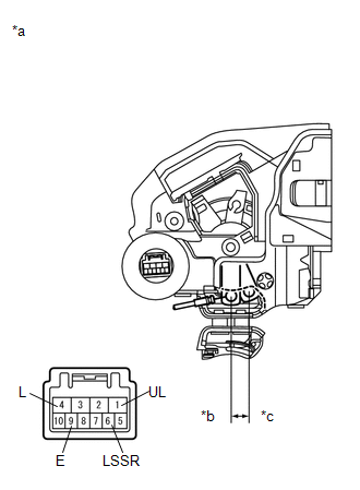
(b) Check the detection switch.
(1) Measure the resistance according to the value(s) in the table below.
Standard Resistance:
|
Tester Connection |
Switch Condition |
Specified Condition |
|---|---|---|
|
6 (LSSR) - 9 (E) |
Lock |
10 kΩ or higher |
|
6 (LSSR) - 9 (E) |
Unlock |
Below 1 Ω |
If the result is not as specified, replace the rear door lock assembly.
 Removal
REMOVAL
CAUTION / NOTICE / HINT
HINT:
Use the same procedure for the RH and LH sides.
The procedure listed below is for the LH side.
PROCEDURE
1. DISCONNECT CABLE FROM NEGATIVE ...
 Installation
INSTALLATION
CAUTION / NOTICE / HINT
HINT:
Use the same procedure for the RH and LH sides.
The procedure listed below is for the LH side.
PROCEDURE
1. INSTALL REAR DOOR INSIDE L ...
Other materials about Toyota 4Runner:
Short in CAN Bus Lines
DESCRIPTION
There may be a short circuit between the CAN bus lines when the resistance between
terminals 6 (CANH) and 14 (CANL) of the DLC3 is below 54 Ω.
Symptom
Trouble Area
The resistance between terminals 6 (CANH ...
Removal
REMOVAL
CAUTION / NOTICE / HINT
CAUTION:
Wear protective gloves. Sharp areas on the parts may injure your hands.
HINT:
Use the same procedure for the power seat RH and power seat LH sides.
The procedure listed below is for the power seat LH ...

0.0179