Toyota 4Runner: Installation
INSTALLATION
PROCEDURE
1. INSTALL COOLER DRYER
(a) Using pliers, install the cooler dryer.
|
(b) Apply a sufficient amount of compressor oil to the contact surfaces of a new O-ring and the cap. Compressor oil: ND-OIL 8 or equivalent |
|
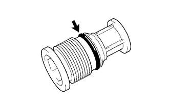
(c) Install the O-ring to the cap.
(d) Using a 14 mm socket hexagon wrench, install the cap to the modulator.
Torque:
2.9 N·m {30 kgf·cm, 26 in·lbf}
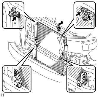
2. INSTALL COOLER CONDENSER ASSEMBLY
|
(a) Install the cooler condenser with the 3 bolts as shown in the illustration. Torque: for bolt A : 5.4 N·m {55 kgf·cm, 48 in·lbf} for bolt B : 4.4 N·m {44 kgf·cm, 39 in·lbf} |
|
3. CONNECT NO. 1 COOLER CONDENSER BRACKET
(a) Connect the No. 1 cooler condenser bracket with the bolt.
4. CONNECT NO. 2 COOLER CONDENSER BRACKET
(a) Connect the No. 2 cooler condenser bracket with the bolt.
5. CONNECT COOLER REFRIGERANT LIQUID PIPE A
(a) Remove the attached vinyl tape from the pipe and the connecting part of the cooler condenser.
(b) Sufficiently apply compressor oil to a new O-ring and the fitting surface of the liquid pipe A joint.
Compressor oil:
ND-OIL 8 or equivalent
(c) Install the O-ring to liquid pipe A.
(d) Connect liquid pipe A to the cooler condenser with the bolt.
Torque:
5.4 N·m {55 kgf·cm, 48 in·lbf}
NOTICE:
- When tightening the bolts, do not allow any tools to contact the pipe.
- When tightening the bolts, hold a part of the pipe near the connector.
6. CONNECT DISCHARGE HOSE SUB-ASSEMBLY
(a) Remove the attached vinyl tape from the hose and the connecting part of the cooler condenser.
(b) Sufficiently apply compressor oil to a new O-ring and the fitting surface of the discharge hose joint.
Compressor oil:
ND-OIL 8 or equivalent
(c) Install the O-ring to the discharge hose.
(d) Connect the discharge hose to the cooler condenser with the bolt.
Torque:
5.4 N·m {55 kgf·cm, 48 in·lbf}
NOTICE:
- When tightening the bolt, do not allow any tools to contact the pipe.
- When tightening the bolt, hold a part of the pipe near the connector.
7. CHARGE REFRIGERANT
.gif)
8. INSTALL RADIATOR ASSEMBLY
(a) Install the radiator assembly (See page
).
9. ADD ENGINE COOLANT
(a) Add the engine coolant (See page ).
10. WARM UP ENGINE
11. CHECK FOR ENGINE COOLANT LEAK
(a) Check for engine coolant leak (See page
).
12. CHECK FOR REFRIGERANT GAS LEAK
 On-vehicle Inspection
ON-VEHICLE INSPECTION
PROCEDURE
1. INSPECT COOLER CONDENSER ASSEMBLY
(a) If the fins of the cooler condenser are dirty, clean them with water. Dry
the fins with compressed air.
NOTICE:
Do not d ...
 Removal
REMOVAL
PROCEDURE
1. DRAIN ENGINE COOLANT
(a) Drain engine coolant (See page ).
2. REMOVE RADIATOR ASSEMBLY
(a) Remove the radiator assembly (See page ).
3. RECOVER REFRIGERANT FROM REFRIGERAT ...
Other materials about Toyota 4Runner:
How To Proceed With Troubleshooting
CAUTION / NOTICE / HINT
HINT:
Use these procedures to troubleshoot the theft deterrent system.
*: Use the Techstream.
The troubleshooting procedures for the theft deterrent system are based
on the premise that the door lock control sys ...
Inspection
INSPECTION
PROCEDURE
1. INSPECT FRONT POWER WINDOW REGULATOR MOTOR ASSEMBLY LH
(a) Check that the motor gear rotates smoothly as follows.
NOTICE:
Do not apply positive (+) battery voltage to any terminals except terminal
2 (B) to avoid ...

0.0278