Toyota 4Runner: Installation
INSTALLATION
PROCEDURE
1. INSTALL LOWER NO. 1 INSTRUMENT PANEL AIRBAG ASSEMBLY
|
(a) Connect the connector. NOTICE: When handling the airbag connector, take care not to damage the airbag wire harness. |
|
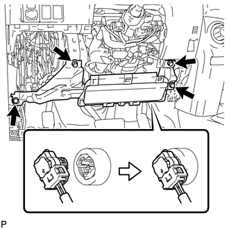
(b) Install the airbag assembly with the 4 bolts.
Torque:
10 N·m {102 kgf·cm, 7 ft·lbf}
2. INSTALL LOWER INSTRUMENT PANEL FINISH PANEL SUB-ASSEMBLY
.gif)
3. INSTALL NO. 1 INSTRUMENT CLUSTER FINISH PANEL GARNISH
4. INSTALL COWL SIDE TRIM BOARD LH
5. INSTALL DOOR SCUFF PLATE ASSEMBLY LH
6. CONNECT CABLE TO NEGATIVE BATTERY TERMINAL
NOTICE:
When disconnecting the cable, some systems need to be initialized after the cable
is reconnected (See page ).
7. CHECK SRS WARNING LIGHT
(a) Check the SRS warning light (See page ).
 Removal
REMOVAL
PROCEDURE
1. DISCONNECT CABLE FROM NEGATIVE BATTERY TERMINAL
CAUTION:
Wait at least 90 seconds after disconnecting the cable from the negative (-)
battery terminal to disable the SRS sys ...
 Disposal
DISPOSAL
CAUTION / NOTICE / HINT
CAUTION:
Before performing pre-disposal deployment of any SRS part, review and closely
follow all applicable environmental and hazardous material regulations. Pre ...
Other materials about Toyota 4Runner:
Reassembly
REASSEMBLY
PROCEDURE
1. INSTALL TRANSFER POSITION SWITCH (for VF2BM)
2. INSTALL TRANSFER POSITION SWITCH (for VF4BM)
3. INSTALL NO. 2 BOX BOTTOM MAT (for 2WD)
(a) Attach the 4 claws to install the No. 2 box bottom mat.
4. INSTALL FRONT UPPER CONSOL ...
System Description
SYSTEM DESCRIPTION
1. GENERAL
(a) The air conditioning system has the following controls.
Control
Outline
Manual Control
The air conditioning amplifier assembly controls the damper positions
(air inlet c ...

0.0067