Toyota 4Runner: System Description
SYSTEM DESCRIPTION
1. GENERAL
(a) The air conditioning system has the following controls.
|
Control |
Outline |
|
|---|---|---|
|
Manual Control |
The air conditioning amplifier assembly controls the damper positions (air inlet control damper, air mix control damper and mode control damper) and blower speed in accordance with the positions of the switches (temperature control dial, blower dial, mode operation switch and REC/FRS switch). |
|
|
Air Inlet Control |
Drives the recirculation damper servo sub-assembly according to the operation of the REC/FRS switch and moves the dampers to the fresh or recirculation position. |
|
|
Compressor Control |
The air conditioning amplifier assembly compares the A/C pulley speed signals, which are transmitted by the ECM (crankshaft position sensor). When the air conditioning amplifier assembly determines that the A/C pulley is locked, it turns off the magnet clutch assembly. |
|
|
Defroster Control |
Defroster control logic is used to improve defroster performance. |
|
|
Defroster Fresh Air Mode Switching Control |
Defroster fresh air mode switching control changes the system from recirculation air mode to fresh air mode to improve defroster performance. |
|
|
MAX Air Conditioning Control |
When the temperature control dial is in the MAX A/C position, the air conditioning amplifier assembly turns the air conditioning compressor on and activates the recirculation damper servo sub-assembly to set the air inlet control damper to the recirculation position*, thereby improving cooling efficiency. |
|
|
Rear Defogger Control |
When the ignition switch is ON and the rear defogger switch is pushed, the system is activated to keep the defogger heater on for approx. 15 minutes. However, the operating time of the rear defogger can be extended up to approx. 255 minutes when both of the following requirements are met:
|
|
|
Diagnosis |
A Diagnostic Trouble Code (DTC) is stored in memory when the air conditioning amplifier assembly detects a problem with the air conditioning system. |
|
- *: w/o DEF, FOOT/DEF mode
2. MODE POSITION AND DAMPER OPERATION
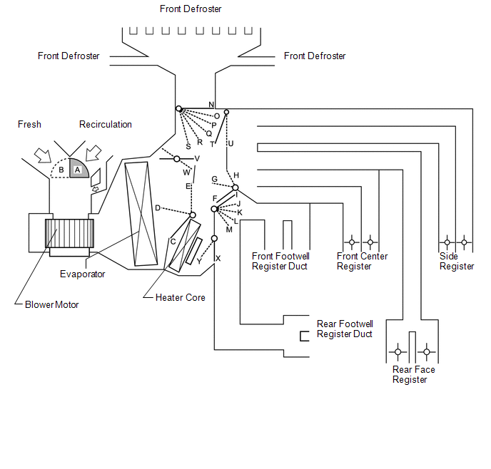 Function of Main Damper
|
Control Damper |
Operation Position |
Damper Position |
Operation |
|---|---|---|---|
|
Air Inlet Control Damper |
Fresh |
A |
Brings in fresh air. |
|
Recirculation |
B |
Recirculates internal air. |
|
|
Air Mix Control Damper |
MAX COOL to MAX HOT |
E - D - C |
Varies the mixture of cold air and hot air in order to regulate the temperature continuously from hot to cool. |
|
MAX COOL Damper |
MAX COOL |
V |
Open in the MAX COOL position. |
|
Except MAX COOL |
W |
Close in all position except MAX COOL position. |
|
|
MAX HOT Damper |
MAX HOT |
Y |
Open in the MAX HOT position. |
|
Except MAX HOT |
X |
Closed in all position except MAX HOT position. |
|
|
Mode Control Damper |
Face .png) |
F, I, N, T, X |
Air blows out of the front center registers, side registers and rear face registers. |
|
Bi-level .png) |
G, L, N, T, X |
Air blows out of the front center registers, side registers, rear face registers and front and rear footwell register ducts. |
|
|
Foot .png) |
H, M, P, T, W, Y (MAX HOT position) H, M, O, T, X (Except MAX HOT position) |
Air blows out of the front and rear footwell register ducts. In addition, air blows out slightly from the front defroster, side registers, front center registers and rear face registers. |
|
|
Foot/Def .png) |
H, K, R, T, W, Y (MAX HOT position) H, M, Q, T, X (Except MAX HOT position) |
Defrosts the windshield through the front defroster and side registers while air is also blown out from the front and rear footwell register ducts. In addition, air blows out slightly from the front center registers and rear face registers. |
|
|
Def .png) |
H, I, S, U, X |
Defrosts the windshield through the front defrosters. |
3. AIR OUTLETS AND AIRFLOW VOLUME
.png)
|
Indication (Mode) |
Front Center Register |
Side Register |
Front Footwell Register |
Rear Face Register |
Rear Footwell Register |
Front Defroster |
|---|---|---|---|---|---|---|
|
A |
B |
C |
D |
E |
F |
|
|
Face |
.png) |
|
- |
.png) |
- |
- |
|
Bi-level |
.png) |
|
|
|
|
- |
|
Foot |
.png) |
|
|
|
|
|
|
Foot/Def |
|
|
|
|
|
|
|
Def |
- |
- |
- |
- |
- |
|
HINT:
The size of the circle indicates the proportion of airflow volume.
4. A/C LOCK SENSOR
The A/C lock sensor sends A/C pulley speed signals to the air conditioning amplifier assembly. The air conditioning amplifier assembly determines whether the A/C compressor is locked or not by using those signals and engine speed signals.
5. NO. 1 COOLER THERMISTOR
The No. 1 cooler thermistor detects the temperature of the cool air immediately after it passes through the evaporator in the form of resistance changes, and outputs the temperature to the air conditioning amplifier assembly.
6. BLOWER WITH FAN MOTOR SUB-ASSEMBLY
The blower with fan motor sub-assembly has a built-in blower controller, and is controlled by the air conditioning amplifier assembly using duty control.
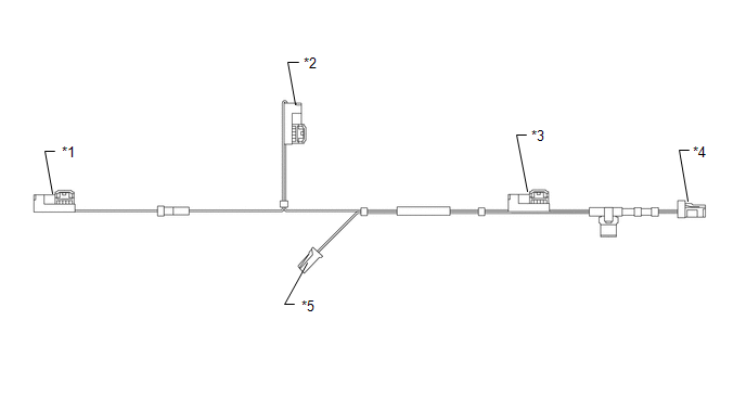
7. AIR CONDITIONING HARNESS ASSEMBLY (BUS CONNECTOR)
(a) A BUS connector is used in the wire harness that connects the servo motor to the air conditioning amplifier assembly.
|
Connector Type |
Connected to |
|---|---|
|
*1: Bus connector |
Damper servo sub-assembly LH (mode damper servo) |
|
*2: Bus connector |
Damper servo sub-assembly RH (air mix damper servo) |
|
*3: Bus connector |
Recirculation damper servo sub-assembly |
|
*4: Bus connector |
Air conditioning amplifier assembly |
|
*5: Connector |
No. 1 cooler thermistor |
(b) Each BUS connector has a built-in communication/driver IC which communicates with each servo motor connector, actuates the servo motor, and has a position detection function.
.png)
8. SERVO MOTOR
(a) The pulse pattern type servo motor detects the relative position using 2-bit on/off signals.
The forward and reverse revolutions of this motor are detected using two signals, A and B, which output four types of patterns. The air conditioning amplifier assembly counts the number of pulse patterns in order to determine the stopped position.
.png)
9. QUICK HEATER ASSEMBLY (w/ PTC Heater)
(a) General
(1) The PTC heater is located above the heater core in the air conditioner unit.
(2) The PTC heater consists of a PTC element, aluminum fins and brass plates. When current is applied to the PTC element, it generates heat to warm the air that passes through the unit.
.png)
(b) PTC Heater Operating Conditions
(1) The on/off operation of the PTC heater is controlled by the air conditioning amplifier assembly in accordance with the engine coolant temperature, ambient temperature, engine speed, air mix setting and electrical load (generator power ratio).
For example, the number of operating PTC heaters varies according to engine coolant temperature as shown in the graph below.
.png)
10. COOLER THERMISTOR (AMBIENT TEMPERATURE SENSOR)
The cooler thermistor (ambient temperature sensor) detects the outside temperature based on changes in the resistance of its built-in thermistor and sends a signal to the air conditioning amplifier assembly.
 Precaution
PRECAUTION
1. IF ANY OF FOLLOWING CONDITIONS ARE MET, KEEP ENGINE IDLING (ENGINE SPEED AT
LESS THAN 2000 RPM) WITH AIR CONDITIONING SWITCH ON FOR AT LEAST 2 MINUTES
Refrigerant gas has been ...
 System Diagram
SYSTEM DIAGRAM
Communication Table
Transmitter
Receiver
Signal
Communication Line
Air conditioning amplifier assembly
ECM
...
Other materials about Toyota 4Runner:
System Description
SYSTEM DESCRIPTION
1. SYSTEM DESCRIPTION
HINT:
The skid control ECU is built into the hydraulic brake booster.
(a) ABS (Anti-lock Brake System)
The ABS helps prevent the wheels from locking when the brakes are applied firmly
or on a slippery surface.
( ...
Portable Player cannot be Operated Using In-vehicle Device or Track Information
is not Displayed on In-vehicle Device
PROCEDURE
1.
CHECK USING ANOTHER "Bluetooth" AUDIO COMPATIBLE VEHICLE OF SAME MODEL
(a) Check if track information is displayed normally on another "Bluetooth" audio
compatible vehicle of the same model.
...

0.0086