Toyota 4Runner: Installation
INSTALLATION
PROCEDURE
1. INSTALL INDOOR NO. 2 ELECTRICAL KEY ANTENNA ASSEMBLY
|
(a) Attach the 2 claws to install the indoor No. 2 electrical key antenna. |
|
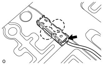
(b) Connect the connector.
2. INSTALL NO. 1 LUGGAGE COMPARTMENT TRIM COVER
.gif)
3. INSTALL REAR FLOOR PAD (w/o Deck Board)
(a) Install the rear floor pad.
4. INSTALL REAR FLOOR CARPET ASSEMBLY (w/o Deck Board)
5. INSTALL REAR FLOOR CARPET ASSEMBLY (w/ Deck Board)
(a) Attach the 4 claws to install the rear floor carpet.
6. INSTALL REAR FLOOR MAT REAR SUPPORT PLATE
7. INSTALL INNER FLOOR SIDE RAIL SUB-ASSEMBLY (w/ Deck Board)
8. INSTALL DECK BOARD ASSEMBLY (w/ Deck Board)
9. INSTALL LUGGAGE COMPARTMENT SIDE COVER SUB-ASSEMBLY LH (w/ Deck Board)
10. INSTALL LUGGAGE COMPARTMENT SIDE COVER SUB-ASSEMBLY RH (w/ Deck Board)
11. INSTALL REAR NO. 2 FLOOR BOARD ASSEMBLY (w/ Deck Board)
12. INSTALL NO. 2 DECK BOARD SUB-ASSEMBLY (w/o Deck Board)
13. INSTALL NO. 2 LUGGAGE COMPARTMENT TRIM COVER (w/ Deck Board, w/o Rear No. 2 Seat)
14. INSTALL NO. 1 DECK BOARD SUB-ASSEMBLY (w/o Deck Board)
15. INSTALL NO. 1 LUGGAGE COMPARTMENT TRIM COVER (w/o Deck Board)
16. INSTALL REAR NO. 2 SEAT ASSEMBLY (w/ Rear No. 2 Seat)
(a) Install the rear No. 2 seat assembly (See page
).
 Components
COMPONENTS
ILLUSTRATION
ILLUSTRATION
ILLUSTRATION
...
 Removal
REMOVAL
PROCEDURE
1. REMOVE REAR NO. 2 SEAT ASSEMBLY
(a) Remove the rear No. 2 seat assembly (See page
).
2. REMOVE NO. 1 LUGGAGE COMPARTMENT TRIM COVER (w/o Deck Board)
3. REMOVE NO. 1 DECK ...
Other materials about Toyota 4Runner:
On-vehicle Inspection
ON-VEHICLE INSPECTION
PROCEDURE
1. INSPECT REFRIGERANT PRESSURE WITH MANIFOLD GAUGE SET
(a) This method uses a manifold gauge set to locate problem areas. Read the manifold
gauge pressure when these conditions are established.
Test conditions:
Te ...
System Diagram
SYSTEM DIAGRAM
Communication Table
Sender
Receiver
Signal
Line
Center airbag sensor assembly
Main body ECU (multiplex network body ECU)
Front seat inner belt LH buckle swit ...

0.0234