Toyota 4Runner: Fuel Sender Open Detected (B1500)
DESCRIPTION
This DTC is stored when the combination meter detects a fuel sender gauge malfunction.
|
DTC Code |
DTC Detection Condition |
Trouble Area |
|---|---|---|
|
B1500 |
IG voltage is 9.5 V or higher and the following condition is met: 1. Fuel sender gauge operation malfunction. |
|
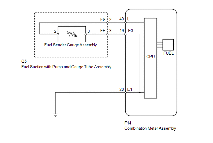
WIRING DIAGRAM
PROCEDURE
|
1. |
READ VALUE USING TECHSTREAM (FUEL SENDER GAUGE) |
(a) Use the Data List to check if the fuel receiver gauge is operating properly
(See page .gif) ).
).
Combination Meter
|
Tester Display |
Measurement Item/Range |
Normal Condition |
Diagnostic Note |
|---|---|---|---|
|
Fuel Input |
Fuel input signal/Min.: 0, Max.: 127.5 |
Current fuel level displayed |
Unit: Liter |
OK:
Fuel amount value displayed on the Techstream is almost the same as needle indication.
Result|
Result |
Proceed to |
|---|---|
|
NG |
A |
|
OK |
B |
| B | .gif) |
REPLACE COMBINATION METER ASSEMBLY |
|
.gif)
|
2. |
CHECK HARNESS AND CONNECTOR (COMBINATION METER - FUEL SUCTION WITH PUMP AND BODY GROUND) |
(a) Disconnect the F14 meter connector.
(b) Disconnect the Q5 gauge connector.
(c) Measure the resistance according to the value(s) in the table below.
Standard Resistance:
|
Tester Connection |
Condition |
Specified Condition |
|---|---|---|
|
F14-40 (L) - Q5-2 (FS) |
Always |
Below 1 Ω |
|
F14-19 (E3) - Q5-3 (FE) |
||
|
F14-20 (E1) - Body ground |
||
|
F14-40 (L) or Q5-2 (FS) - Body ground |
Always |
10 kΩ or higher |
| NG | |
REPAIR OR REPLACE HARNESS OR CONNECTOR |
|
|
3. |
INSPECT FUEL SUCTION WITH PUMP AND GAUGE TUBE ASSEMBLY |
|
(a) Remove the fuel suction with pump and gauge tube assembly (See page
|
|
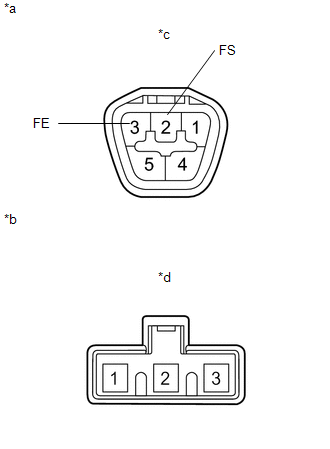
(b) Measure the resistance according to the value(s) in the table below.
Standard Resistance:
|
Tester Connection |
Condition |
Specified Condition |
|---|---|---|
|
A-2 (FS) - B-2 |
Always |
Below 1 Ω |
|
A-3 (FE) - B-3 |
|
*a |
Upper Side |
|
*b |
Lower Side (to Fuel Sender Gauge Assembly) |
|
*c |
Connector A |
|
*d |
Connector B |
| NG | |
REPLACE FUEL SUCTION WITH PUMP AND GAUGE TUBE ASSEMBLY |
|
|
4. |
INSPECT FUEL SENDER GAUGE ASSEMBLY |
|
(a) Remove the fuel sender gauge (See page
|
|
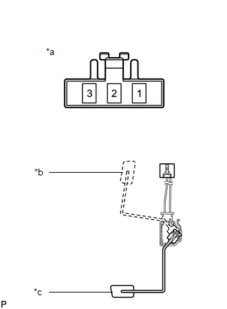
(b) Measure the resistance according to the value(s) in the table below.
Standard Resistance:
|
Tester Connection |
Condition |
Specified Condition |
|---|---|---|
|
2 - 3 |
Float level F (upper) |
12 to 18 Ω |
|
Float level E (lower) |
405 to 415 Ω |
|
*a |
Front view of wire harness connector (to Fuel Sender Gauge Assembly) |
|
*b |
Float level F (upper) |
|
*c |
Float level E (lower) |
| OK | |
REPLACE COMBINATION METER ASSEMBLY |
| NG | |
REPLACE FUEL SENDER GAUGE ASSEMBLY |
 Diagnostic Trouble Code Chart
DIAGNOSTIC TROUBLE CODE CHART
HINT:
If a trouble code is output during the DTC check, inspect the trouble areas for
that code. For details of the code, refer to the "See page" below.
...
 Lost Communication with ECM / PCM "A" (U0100,U0129,U0131,U0151)
DESCRIPTION
The combination meter assembly communicates with the ECM via the CAN communication
system (CAN No. 1 Bus).
DTC Code.
DTC Detection Condition
Trouble Ar ...
Other materials about Toyota 4Runner:
How To Proceed With Troubleshooting
CAUTION / NOTICE / HINT
HINT:
Use the following procedure to troubleshoot the rear view monitor system.
PROCEDURE
1.
VEHICLE BROUGHT TO WORKSHOP
NEXT
...
Tachometer Malfunction
DESCRIPTION
In this circuit, the meter CPU receives engine speed signals from the ECM using
the CAN communication system. The meter CPU displays the engine speed, which is
calculated based on the data received from the ECM.
WIRING DIAGRAM
PROCEDURE
...

0.0098