Toyota 4Runner: Installation
INSTALLATION
PROCEDURE
1. INSTALL BRAKE BOOSTER GASKET
(a) Install a new brake booster gasket to the hydraulic brake booster.
2. INSTALL HYDRAULIC BRAKE BOOSTER ASSEMBLY
(a) Install the hydraulic brake booster assembly with the 4 nuts.
Torque:
14 N·m {145 kgf·cm, 10 ft·lbf}
|
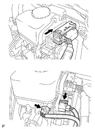
(b) Connect the 4 brake lines to the correct positions of the hydraulic brake booster assembly as shown in the illustration. HINT:
|
|
.png)
(c) Using a union nut wrench, connect the 4 brake lines to the hydraulic brake booster assembly.
Torque:
15 N·m {155 kgf·cm, 11 ft·lbf}
NOTICE:
Use the formula to calculate special torque values for situations where a union
nut wrench is combined with a torque wrench (See page
.gif) ).
).
|
(d) Connect the 3 connectors to the hydraulic brake booster assembly. |
|
3. INSTALL PUSH ROD PIN
4. INSTALL LOWER NO. 1 INSTRUMENT PANEL AIRBAG ASSEMBLY
(a) Install the lower No. 1 instrument panel airbag assembly (See page
).
5. CONNECT CABLE TO NEGATIVE BATTERY TERMINAL
NOTICE:
When disconnecting the cable, some systems need to be initialized after the cable
is reconnected (See page ).
6. BLEED BRAKE SYSTEM
7. CHECK AND ADJUST BRAKE PEDAL
(a) Check and adjust brake pedal (See page ).
8. INSPECT BRAKE MASTER CYLINDER OPERATION
(a) Inspect the brake master cylinder operation (See page
).
9. PERFORM YAW RATE AND ACCELERATION SENSOR ZERO POINT CALIBRATION
(a) Perform the yaw rate and acceleration sensor zero point calibration (See
page ).
 Reassembly
REASSEMBLY
PROCEDURE
1. INSTALL BRAKE BOOSTER PISTON SIB-ASSEMBLY
(a) Apply a light coat of lithium soap base glycol grease to a new piston.
(b ...
 Disposal
DISPOSAL
PROCEDURE
1. DISPOSE OF BRAKE BOOSTER ACCUMULATOR ASSEMBLY
(a) Place the brake booster accumulator assembly in a vise and cover
it with cloth.
...
Other materials about Toyota 4Runner:
Radio Receiver Power Source Circuit
DESCRIPTION
This is the power source circuit to operate the radio and display receiver assembly.
WIRING DIAGRAM
CAUTION / NOTICE / HINT
NOTICE:
Inspect the fuses for circuits related to this system before performing the following
inspection procedure. ...
Operating a Bluetooth® enabled portable player
Selecting an album
Press “∨” or “∧” on .
Selecting tracks
Press “∧” or “∨” on .
Playing and pausing tracks
Press .
Fast-forwarding and reversing tracks
Press and hold “∧” or “∨” on .
Switching the display
Press .
...

0.0265