Toyota 4Runner: Installation
INSTALLATION
PROCEDURE
1. INSTALL PARKING PEDAL PAD
(a) Install the parking pedal pad.
2. INSTALL NO. 1 PARKING BRAKE CABLE ASSEMBLY
(a) Temporarily install the No. 1 parking brake cable assembly with the adjusting nut and lock nut.
(b) Install the No. 1 parking brake cable assembly with the 4 nuts and 3 bolts.
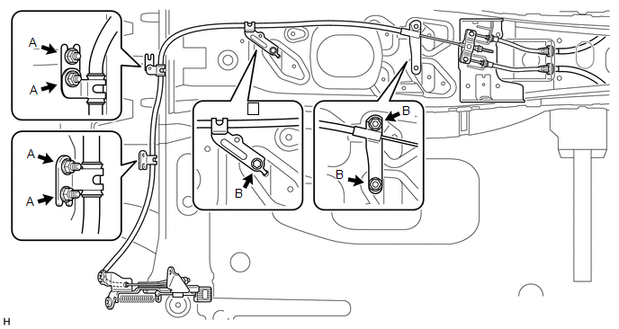
Torque:
for nut A :
6.0 N·m {61 kgf·cm, 53 in·lbf}
for bolt B :
13 N·m {127 kgf·cm, 9 ft·lbf}
|
(c) Pass the No. 1 parking brake cable through the parking brake pedal. |
|
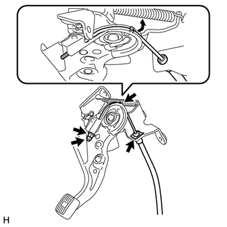
(d) Install the clip.
(e) Bend the parking brake pedal claw.
(f) Temporarily install the adjusting nut and lock nut to the No. 1 parking brake cable.
3. INSTALL PARKING BRAKE CONTROL PEDAL ASSEMBLY
(a) Install the parking brake control pedal assembly with the 3 nuts.
Torque:
13 N·m {127 kgf·cm, 9 ft·lbf}
(b) Connect the parking brake switch connector.
4. INSTALL TRANSMISSION FLOOR SHIFT ASSEMBLY
(a) Transmission type A750F:
Install the transmission floor shift assembly (See page
.gif) ).
).
(b) Transmission type A750E:
Install the transmission floor shift assembly (See page
).
5. INSTALL AIRBAG SENSOR ASSEMBLY
6. INSTALL YAW RATE AND ACCELERATION SENSOR
7. INSTALL TIRE PRESSURE WARNING ECU
8. INSTALL TURN SIGNAL FLASHER ASSEMBLY
9. INSTALL REAR CONSOLE BOX ASSEMBLY
(a) Install the rear console box assembly (See page
).
10. INSTALL LOWER NO. 1 INSTRUMENT PANEL AIRBAG ASSEMBLY
(a) Install the lower No. 1 instrument panel airbag assembly (See page
).
11. ADJUST PARKING BRAKE SHOE CLEARANCE AND PARKING BRAKE PEDAL TRAVEL
12. CONNECT CABLE TO NEGATIVE BATTERY TERMINAL
NOTICE:
When disconnecting the cable, some systems need to be initialized after the cable
is reconnected (See page ).
 Removal
REMOVAL
PROCEDURE
1. DISCONNECT CABLE FROM NEGATIVE BATTERY TERMINAL
CAUTION:
Wait at least 90 seconds after disconnecting the cable from the negative (-)
battery terminal to disable the SRS sys ...
 Parking Brake Switch
Components
COMPONENTS
ILLUSTRATION
Removal
REMOVAL
PROCEDURE
1. DISCONNECT CABLE FROM NEGATIVE BATTERY TERMINAL
CAUTION:
Wait at least 90 seconds after disconnecting the cable from the n ...
Other materials about Toyota 4Runner:
System Description
SYSTEM DESCRIPTION
1. FRONT POWER SEAT CONTROL SYSTEM DESCRIPTION
The driver seat is equipped with slide, reclining, lifter, front vertical
and lumbar support adjustment functions.
The passenger seat is equipped with slide and reclining adjust ...
Disabling the TRAC/VSC systems (2WD models)
If the vehicle gets stuck in fresh snow or mud, the TRAC/VSC systems may
reduce power from the engine to the wheels. You may need to turn the system off
to enable you to rock the vehicle in order to free it.
Turning off the TRAC system only (turning on th ...

0.0092