Toyota 4Runner: Removal
REMOVAL
PROCEDURE
1. DISCONNECT CABLE FROM NEGATIVE BATTERY TERMINAL
CAUTION:
Wait at least 90 seconds after disconnecting the cable from the negative (-) battery terminal to disable the SRS system.
NOTICE:
When disconnecting the cable, some systems need to be initialized after the cable
is reconnected (See page .gif) ).
).
2. REMOVE LOWER NO. 1 INSTRUMENT PANEL AIRBAG ASSEMBLY
(a) Remove the lower No. 1 instrument panel airbag assembly (See page
.gif) ).
).
3. REMOVE REAR CONSOLE BOX ASSEMBLY
(a) Remove the rear console box assembly (See page
.gif) ).
).
4. REMOVE AIRBAG SENSOR ASSEMBLY
.gif)
5. REMOVE YAW RATE AND ACCELERATION SENSOR
.gif)
6. REMOVE TURN SIGNAL FLASHER ASSEMBLY
.gif)
7. REMOVE TIRE PRESSURE WARNING ECU
.gif)
8. REMOVE PARKING BRAKE CONTROL PEDAL ASSEMBLY
|
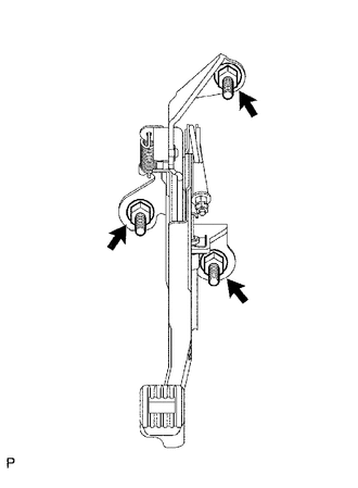
(a) Release the parking brake pedal. |
|
(b) Disconnect the parking brake switch connector.
(c) Remove the 3 nuts and parking brake control pedal assembly.
9. REMOVE TRANSMISSION FLOOR SHIFT ASSEMBLY
(a) Transmission type A750F:
Remove the transmission floor shift assembly (See page
.gif) ).
).
(b) Transmission type A750E:
Remove the transmission floor shift assembly (See page
.gif) ).
).
10. REMOVE NO. 1 PARKING BRAKE CABLE ASSEMBLY
|
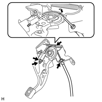
(a) Remove the lock nut and adjusting nut. |
|
(b) Remove the clip.
(c) Pull up the parking brake pedal claw.
(d) Remove the No. 1 parking brake cable assembly.
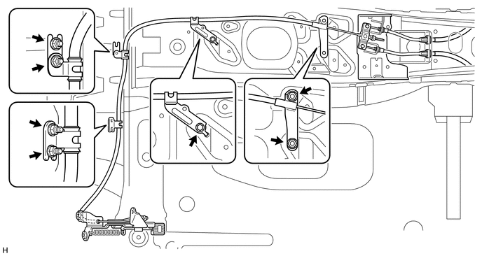
(e) Remove the 4 nuts and 3 bolts from the No. 1 parking brake cable assembly.

|
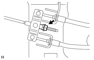
(f) Remove the lock nut, adjusting nut and No. 1 parking brake cable assembly from the parking brake equalizer. |
|
11. REMOVE PARKING PEDAL PAD
(a) Remove the parking pedal pad.
 Components
COMPONENTS
ILLUSTRATION
ILLUSTRATION
...
 Installation
INSTALLATION
PROCEDURE
1. INSTALL PARKING PEDAL PAD
(a) Install the parking pedal pad.
2. INSTALL NO. 1 PARKING BRAKE CABLE ASSEMBLY
(a) Temporarily install the No. 1 parking brake cable assembly ...
Other materials about Toyota 4Runner:
Motor LH Over Temperature (64,65)
DESCRIPTION
When the side auto step controller ECU assembly detects the overheating in the
system, it stops the operation of the automatic running board.
DTC No.
Detection Condition
Trouble Area
64
...
Reassembly
REASSEMBLY
CAUTION / NOTICE / HINT
HINT:
Use the same procedure for the RH and LH sides.
The procedure listed below is for the LH side.
PROCEDURE
1. INSTALL FRONT TURN SIGNAL LIGHT BULB
(a) Install the front turn signal light bulb to th ...
0.0255


