
Toyota 4Runner: Parking Brake Switch
Components
COMPONENTS
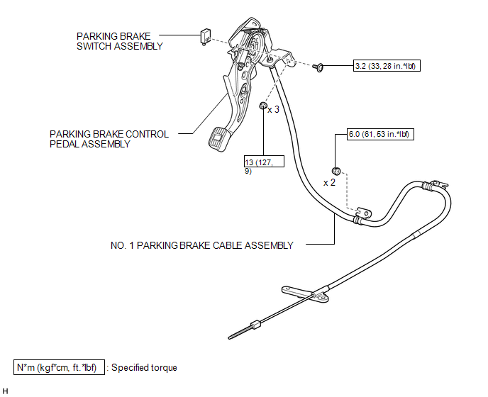
ILLUSTRATION
Removal
REMOVAL
PROCEDURE
1. DISCONNECT CABLE FROM NEGATIVE BATTERY TERMINAL
CAUTION:
Wait at least 90 seconds after disconnecting the cable from the negative (-) battery terminal to disable the SRS system.
NOTICE:
When disconnecting the cable, some systems need to be initialized after the cable
is reconnected (See page .gif) ).
).
2. REMOVE LOWER NO. 1 INSTRUMENT PANEL AIRBAG ASSEMBLY
(a) Remove the lower No. 1 instrument panel airbag assembly (See page
).
3. REMOVE TURN SIGNAL FLASHER ASSEMBLY
4. REMOVE TIRE PRESSURE WARNING ECU
5. DISCONNECT PARKING BRAKE CONTROL PEDAL ASSEMBLY
(a) Partially remove the front floor carpet.
|
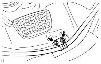
(b) Remove the 2 nuts and disconnect the No. 1 parking brake cable assembly from the body. |
|
(c) Disconnect the parking brake switch connector.
|
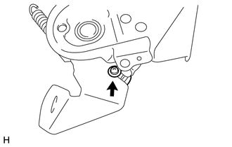
(d) Remove the 3 nuts and disconnect the parking brake control pedal assembly from the body. |
|
.png)
6. REMOVE PARKING BRAKE SWITCH ASSEMBLY
|
(a) Remove the screw and parking brake switch assembly from the parking brake control pedal assembly. |
|
Inspection
INSPECTION
PROCEDURE
1. INSPECT PARKING BRAKE SWITCH ASSEMBLY
(a) Measure the resistance according to the value(s) in the table below.
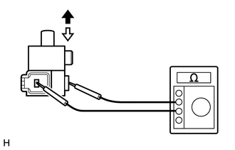
Standard Resistance:
|
Tester Connection |
Switch Condition |
Specified Condition |
|---|---|---|
|
Switch connector - Switch body |
On (Shaft is not pressed) |
Below 1 Ω |
|
Off (Shaft is pressed) |
10 kΩ or higher |
.png) |
On |
.png) |
Off |
If the result is not as specified, replace the parking brake switch assembly.
Installation
INSTALLATION
PROCEDURE
1. INSTALL PARKING BRAKE SWITCH ASSEMBLY
(a) Install the parking brake switch assembly to the parking brake control pedal assembly with the screw.
Torque:
3.2 N·m {33 kgf·cm, 28 in·lbf}
2. INSTALL PARKING BRAKE CONTROL PEDAL ASSEMBLY
(a) Temporarily install the parking brake control pedal assembly with the 3 nuts.
(b) Tighten the 3 nuts.
Torque:
13 N·m {127 kgf·cm, 9 ft·lbf}
(c) Connect the parking brake switch connector.
(d) Install the No. 1 parking brake cable assembly to the body with the 2 nuts.
Torque:
6.0 N·m {61 kgf·cm, 53 in·lbf}
3. INSTALL TIRE PRESSURE WARNING ECU
.gif)
4. INSTALL TURN SIGNAL FLASHER ASSEMBLY
5. INSTALL LOWER NO. 1 INSTRUMENT PANEL AIRBAG ASSEMBLY
(a) Install the lower No. 1 instrument panel airbag assembly (See page
).
6. CONNECT CABLE TO NEGATIVE BATTERY TERMINAL
NOTICE:
When disconnecting the cable, some systems need to be initialized after the cable
is reconnected (See page ).
 Installation
INSTALLATION
PROCEDURE
1. INSTALL PARKING PEDAL PAD
(a) Install the parking pedal pad.
2. INSTALL NO. 1 PARKING BRAKE CABLE ASSEMBLY
(a) Temporarily install the No. 1 parking brake cable assembly ...

Other materials about Toyota 4Runner:
Dtc Check / Clear
DTC CHECK / CLEAR
1. CHECK DTC
(a) Connect the Techstream to the DLC3.
(b) Turn the engine switch on (IG).
(c) Turn the Techstream on.
(d) Enter the following menus: Body Electrical / (desired system) / DTC.
(e) Read the DTCs.
2. CLEAR DTC
(a) Connect ...
Downhill Assist Control Switch
Components
COMPONENTS
ILLUSTRATION
Removal
REMOVAL
PROCEDURE
1. REMOVE DRIVE MONITOR SWITCH
2. REMOVE MAP LIGHT ASSEMBLY
3. REMOVE DOWNHILL ASSIST CONTROL SWITCH
(a) Disconnect the 2 connectors.
...

0.0253