Toyota 4Runner: Interior Light Auto Cut Circuit
DESCRIPTION
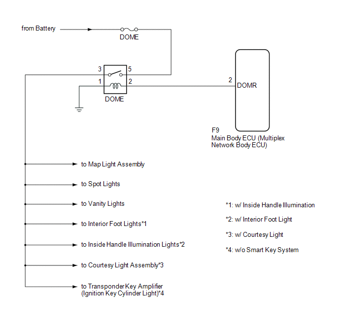
The main body ECU (multiplex network body ECU) controls operation of the DOME relay in order to supply power to the interior lights. When battery saving control operates while the interior lights are on, the main body ECU (multiplex network body ECU) opens the DOME relay to turn off the lights.
WIRING DIAGRAM
CAUTION / NOTICE / HINT
NOTICE:
Inspect the fuses for circuits related to this system before performing the following inspection procedure.
PROCEDURE
|
1. |
CHECK SYMPTOMS |
(a) Check symptoms.
Result|
Result |
Proceed to |
|---|---|
|
All the interior lights that receive power via the DOME relay do not illuminate. |
A |
|
Battery saving function does not operate. |
B |
| B | .gif) |
GO TO STEP 4 |
|
.gif)
|
2. |
INSPECT DOME RELAY |
(a) Remove the DOME relay from the engine room relay block, junction block.
(b) Inspect the DOME relay (See page .gif) ).
).
| NG | |
REPLACE DOME RELAY |
|
|
3. |
CHECK HARNESS AND CONNECTOR (DOME FUSE - DOME RELAY) |
|
(a) Measure the voltage according to the value(s) in the table below. Standard Voltage:
|
|
.png)
| NG | |
REPAIR OR REPLACE HARNESS OR CONNECTOR |
|
|
4. |
PERFORM ACTIVE TEST USING TECHSTREAM |
(a) Using the Techstream, perform the Active Test (See page
).
HINT:
In the Active Test, check the interior light operating state.
Main Body|
Tester Display |
Test Part |
Control Range |
Diagnostic Note |
|---|---|---|---|
|
Relay for Interior Light Auto Cut Function |
DOME relay |
ON/OFF |
- |
OK:
Battery saving control operates.
HINT:
- In the Active Test, selecting the DOME relay ON or OFF turns the interior light on or off.
- After turning the ignition switch to ON, proceed to the preceding screen of the active test screen with the Techstream and turn the ignition switch off, and perform the active test.
| OK | |
PROCEED TO NEXT SUSPECTED AREA SHOWN IN PROBLEM SYMPTOMS TABLE |
|
|
5. |
INSPECT DOME RELAY |
(a) Remove the DOME relay from the engine room relay block, junction block.
(b) Inspect the DOME relay (See page ).
| NG | |
REPLACE DOME RELAY |
|
|
6. |
CHECK HARNESS AND CONNECTOR (DOME RELAY - MAIN BODY ECU, BODY GROUND) |
(a) Remove the Main body ECU (See page ).
(b) Measure the resistance according to the value(s) in the table below.
Standard Resistance:
|
Tester Connection |
Condition |
Specified Condition |
|---|---|---|
|
DOME relay terminal 2 - F9-2 (DOMR) |
Always |
Below 1 Ω |
|
DOME relay terminal 1 - Body ground |
Always |
Below 1 Ω |
|
F9-2 (DOMR) - Body ground |
Always |
10 kΩ or higher |
| OK | |
PROCEED TO NEXT SUSPECTED AREA SHOWN IN PROBLEM SYMPTOMS TABLE |
| NG | |
REPAIR OR REPLACE HARNESS OR CONNECTOR |
 Door Courtesy Switch Circuit
DESCRIPTION
The main body ECU (multiplex network body ECU) receives a door open/closed signal
from each door courtesy light switch.
WIRING DIAGRAM
PROCEDURE
1.
READ VALU ...
 Inside Handle Illumination Light Circuit
DESCRIPTION
The main body ECU (multiplex network body ECU) controls the inside handle illumination.
WIRING DIAGRAM
CAUTION / NOTICE / HINT
NOTICE:
Inspect the fuses for circuits related to this ...
Other materials about Toyota 4Runner:
Air Inlet Damper Control Servo Motor Circuit (B1442)
DESCRIPTION
The recirculation damper servo sub-assembly sends pulse signals to inform the
No. 1 air conditioning amplifier assembly of the damper position. The No. 1 air
conditioning amplifier assembly activates the motor (normal or reverse) based on
th ...
Open Circuit in Transfer 4WD Position Switch Circuit (C1258,C1340)
DESCRIPTION
DTC Code
DTC Detection Condition
Trouble Area
C1258*1
C1340*2
An open circuit is detected in the EXI circuit of the skid control ECU.
Harness or connector
...

0.0175