Toyota 4Runner: Inside Handle Illumination Light Circuit
DESCRIPTION
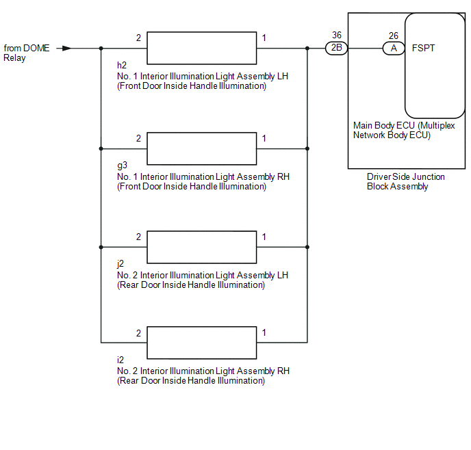
The main body ECU (multiplex network body ECU) controls the inside handle illumination.
WIRING DIAGRAM
CAUTION / NOTICE / HINT
NOTICE:
Inspect the fuses for circuits related to this system before performing the following inspection procedure.
PROCEDURE
|
1. |
CHECK DOOR INSIDE HANDLE ILLUMINATION |
(a) Check the each door inside handle illumination.
Result|
Result |
Proceed to |
|---|---|
|
Front door inside handle illumination does not come on. |
A |
|
Rear door inside handle illumination does not come on. |
B |
| B | .gif) |
GO TO STEP 5 |
|
.gif)
|
2. |
INSPECT NO. 1 INTERIOR ILLUMINATION LIGHT ASSEMBLY (FRONT DOOR INSIDE HANDLE ILLUMINATION) (LH OR RH) |
|
(a) Remove the No. 1 interior illumination light assembly (front door
inside handle illumination) (See page |
|
(b) Connect a positive (+) lead from the battery to terminal 1 and a negative (-) lead to terminal 2.
(c) Check that the No. 1 interior illumination light assembly (front door inside handle illumination) comes on.
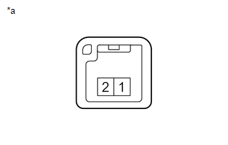
Text in Illustration|
*a |
Component without harness connected (No. 1 Interior Illumination Light Assembly (Front Door Inside Handle Illumination)) |
OK:
No. 1 interior illumination light assembly (front door inside handle illumination) comes on
| NG | |
REPLACE NO. 1 INTERIOR ILLUMINATION LIGHT ASSEMBLY (FRONT DOOR INSIDE HANDLE ILLUMINATION) |
|
|
3. |
CHECK HARNESS AND CONNECTOR (BATTERY - NO. 1 INTERIOR ILLUMINATION LIGHT ASSEMBLY) |
(a) Disconnect the h2*1 or g3*2 No. 1 interior illumination light assembly (front door inside handle illumination) connector.
(b) Measure the voltage according to the value(s) in the table below.
- *1: for LH
- *2: for RH
Standard Voltage:
for LH
|
Tester Connection |
Condition |
Specified Condition |
|---|---|---|
|
h2-2 - Body ground |
Always |
11 to 14 V |
for RH
|
Tester Connection |
Condition |
Specified Condition |
|---|---|---|
|
g3-2 - Body ground |
Always |
11 to 14 V |
| NG | |
REPAIR OR REPLACE HARNESS OR CONNECTOR |
|
|
4. |
CHECK HARNESS AND CONNECTOR (NO. 1 INTERIOR ILLUMINATION - DRIVER SIDE JUNCTION BLOCK) |
(a) Disconnect the h2*1 or g3*2 No. 1 interior illumination light assembly (front door inside handle illumination) connector.
(b) Disconnect the 2B driver side junction block assembly connector.
(c) Measure the resistance according to the value(s) in the table below.
- *1: for LH
- *2: for RH
Standard Resistance (Check for Open):
for LH
|
Tester Connection |
Condition |
Specified Condition |
|---|---|---|
|
h2-1 - 2B-36 |
Always |
Below 1 Ω |
for RH
|
Tester Connection |
Condition |
Specified Condition |
|---|---|---|
|
g3-1 - 2B-36 |
Always |
Below 1 Ω |
Standard Resistance (Check for Short):
for LH
|
Tester Connection |
Condition |
Specified Condition |
|---|---|---|
|
h2-1 or 2B-36 - Body ground |
Always |
10 kΩ or higher |
for RH
|
Tester Connection |
Condition |
Specified Condition |
|---|---|---|
|
g3-1 or 2B-36 - Body ground |
Always |
10 kΩ or higher |
|
Result |
Proceed to |
|---|---|
|
NG |
A |
|
OK |
B |
| A | |
REPAIR OR REPLACE HARNESS OR CONNECTOR |
| B | |
GO TO STEP 8 |
|
5. |
INSPECT NO. 2 INTERIOR ILLUMINATION LIGHT ASSEMBLY (REAR DOOR INSIDE HANDLE ILLUMINATION) (LH OR RH) |
|
(a) Remove the No. 2 interior illumination light assembly (rear door
inside handle illumination) (See page |
|
(b) Connect a positive (+) lead from the battery to terminal 1 and a negative (-) lead to terminal 2.
(c) Check that the No. 2 interior illumination light assembly (rear door inside handle illumination) comes on.
Text in Illustration|
*a |
Component without harness connected (No. 2 Interior Illumination Light Assembly (Rear Door Inside Handle Illumination)) |
OK:
No. 2 interior illumination light assembly (rear door inside handle illumination) comes on
| NG | |
REPLACE NO. 2 INTERIOR ILLUMINATION LIGHT ASSEMBLY (REAR DOOR INSIDE HANDLE ILLUMINATION) |
|
|
6. |
CHECK HARNESS AND CONNECTOR (BATTERY - NO. 2 INTERIOR ILLUMINATION LIGHT ASSEMBLY) |
(a) Disconnect the j2*1 or i2*2 No. 2 interior illumination light (rear door inside handle illumination) connector.
(b) Measure the voltage according to the value(s) in the table below.
- *1: for LH
- *2: for RH
Standard Voltage:
for LH
|
Tester Connection |
Condition |
Specified Condition |
|---|---|---|
|
j2-2 - Body ground |
Always |
11 to 14 V |
for RH
|
Tester Connection |
Condition |
Specified Condition |
|---|---|---|
|
i2-2 - Body ground |
Always |
11 to 14 V |
| NG | |
REPAIR OR REPLACE HARNESS OR CONNECTOR |
|
|
7. |
CHECK HARNESS AND CONNECTOR (NO. 2 INTERIOR ILLUMINATION - DRIVER SIDE JUNCTION BLOCK) |
(a) Disconnect the j2*1 or i2*2 No. 2 interior illumination light (rear door inside handle illumination) connector.
(b) Disconnect the 2B driver side junction block assembly connector.
(c) Measure the resistance according to the value(s) in the table below.
- *1: for LH
- *2: for RH
Standard Resistance (Check for Open):
for LH
|
Tester Connection |
Condition |
Specified Condition |
|---|---|---|
|
j2-1 - 2B-36 |
Always |
Below 1 Ω |
for RH
|
Tester Connection |
Condition |
Specified Condition |
|---|---|---|
|
i2-1 - 2B-36 |
Always |
Below 1 Ω |
Standard Resistance (Check for Short):
for LH
|
Tester Connection |
Condition |
Specified Condition |
|---|---|---|
|
j2-1 or 2B-36 - Body ground |
Always |
10 kΩ or higher |
for RH
|
Tester Connection |
Condition |
Specified Condition |
|---|---|---|
|
i2-1 or 2B-36 - Body ground |
Always |
10 kΩ or higher |
| NG | |
REPAIR OR REPLACE HARNESS OR CONNECTOR |
|
|
8. |
INSPECT DRIVER SIDE JUNCTION BLOCK ASSEMBLY |
(a) Remove the driver side junction block assembly (See page
.gif) ).
).
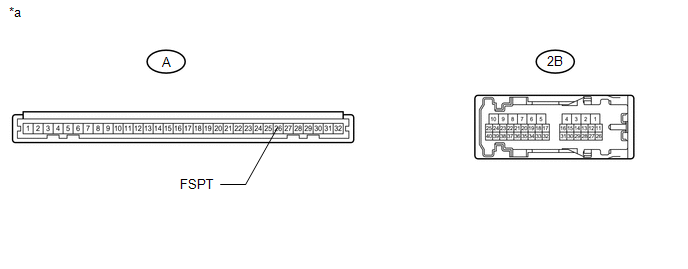 Text in Illustration
|
*a |
Component without harness connected (Driver Side Junction Block Assembly) |
- |
- |
(b) Remove the main body ECU (multiplex network body ECU) from driver side junction block assembly.
(c) Measure the resistance according to the value(s) in the table below.
Standard Resistance:
|
Tester Connection |
Condition |
Specified Condition |
|---|---|---|
|
2B-36 - A-26 (FSPT) |
Always |
Below 1 Ω |
| OK | |
REPLACE MAIN BODY ECU (MULTIPLEX NETWORK BODY ECU) |
| NG | |
REPLACE DRIVER SIDE JUNCTION BLOCK ASSEMBLY |
 Interior Light Auto Cut Circuit
DESCRIPTION
The main body ECU (multiplex network body ECU) controls operation of the DOME
relay in order to supply power to the interior lights. When battery saving control
operates while the int ...
 Luggage Room Light Circuit
DESCRIPTION
The multiplex network door ECU controls the spot light.
WIRING DIAGRAM
CAUTION / NOTICE / HINT
NOTICE:
Inspect the fuses and bulbs for circuits related to this system before perform ...
Other materials about Toyota 4Runner:
Disassembly
DISASSEMBLY
PROCEDURE
1. REMOVE COOLER BRACKET
(a) Detach the clamp.
(b) Remove the screw and cooler bracket.
2. REMOVE MAGNET CLUTCH ASSEMBLY
(a) Clamp the cooler compressor in a vise.
(b) Using SST, hold the magnet clutch hub.
SST: 07112-76060
( ...
Diagnostic Trouble Code Chart
DIAGNOSTIC TROUBLE CODE CHART
HINT:
If a trouble code is output during the DTC check, inspect the trouble areas listed
for that code. For details of the code, refer to the "See page" below.
Certification ECU
DTC Code
Detec ...

0.0093