Toyota 4Runner: Inverter Main Switch
Components
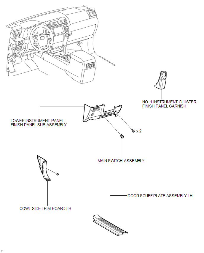
COMPONENTS
ILLUSTRATION
Installation
INSTALLATION
PROCEDURE
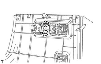
1. INSTALL MAIN SWITCH ASSEMBLY
(a) Attach the 2 claws to install the main switch.
2. INSTALL LOWER INSTRUMENT PANEL FINISH PANEL SUB-ASSEMBLY
.gif)
3. INSTALL COWL SIDE TRIM BOARD LH
4. INSTALL DOOR SCUFF PLATE ASSEMBLY LH
5. INSTALL NO. 1 INSTRUMENT CLUSTER FINISH PANEL GARNISH
Removal
REMOVAL
PROCEDURE
1. REMOVE NO. 1 INSTRUMENT CLUSTER FINISH PANEL GARNISH
.gif)
2. REMOVE DOOR SCUFF PLATE ASSEMBLY LH
3. REMOVE COWL SIDE TRIM BOARD LH
4. REMOVE LOWER INSTRUMENT PANEL FINISH PANEL SUB-ASSEMBLY
5. REMOVE MAIN SWITCH ASSEMBLY
|
(a) Detach the 2 claws and remove the main switch. |
|
 Removal
REMOVAL
PROCEDURE
1. REMOVE NO. 1 INSTRUMENT CLUSTER FINISH PANEL GARNISH
2. REMOVE NO. 2 INSTRUMENT CLUSTER FINISH PANEL GARNISH
3. REMOVE FRONT NO. 1 CONSOLE BOX INSERT
4. REMOVE FRONT ...

Other materials about Toyota 4Runner:
Reverse Signal Circuit
DESCRIPTION
The radio and display receiver assembly receives a reverse signal from the park/neutral
position switch assembly.
WIRING DIAGRAM
PROCEDURE
1.
CHECK HARNESS AND CONNECTOR (REVERSE SIGNAL)
(a) Disconnect the G ...
Taillight Relay Circuit
DESCRIPTION
This is the power source circuit of the clearance warning ECU assembly.
WIRING DIAGRAM
CAUTION / NOTICE / HINT
NOTICE:
Inspect the fuses for circuits related to this system before performing the following
inspection procedure.
PROCEDURE
...

0.026