Toyota 4Runner: Removal
REMOVAL
PROCEDURE
1. REMOVE NO. 1 INSTRUMENT CLUSTER FINISH PANEL GARNISH
.gif)
2. REMOVE NO. 2 INSTRUMENT CLUSTER FINISH PANEL GARNISH
3. REMOVE FRONT NO. 1 CONSOLE BOX INSERT
4. REMOVE FRONT NO. 2 CONSOLE BOX INSERT
5. REMOVE SHIFT LEVER KNOB SUB-ASSEMBLY
6. REMOVE SHIFT LEVER KNOB SUB-ASSEMBLY (for VF2A)
7. REMOVE UPPER CONSOLE PANEL SUB-ASSEMBLY
8. REMOVE NO. 2 CONSOLE BOX RETAINER
9. REMOVE REAR CONSOLE BOX ASSEMBLY
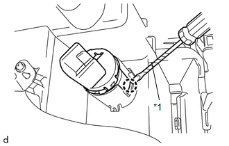
10. REMOVE NO. 1 POWER OUTLET SOCKET ASSEMBLY
(a) Disconnect the power outlet socket assembly connector.
|
(b) Using a screwdriver, detach the claw to remove the No. 1 power outlet socket assembly. Text in Illustration
HINT: Tape the screwdriver tip before use. |
|
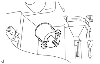
11. REMOVE NO. 1 POWER OUTLET SOCKET COVER
|
(a) Detach the 2 claws to remove the No. 1 power outlet socket cover. |
|
12. REMOVE REAR CONSOLE END PANEL
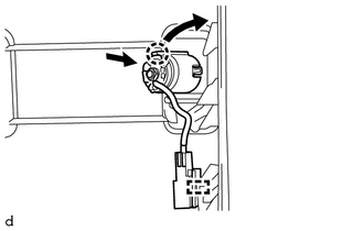
13. REMOVE NO. 3 POWER OUTLET SOCKET ASSEMBLY
(a) Detach the connector clamp.
|
(b) While pulling the claw of the No. 3 power outlet socket assembly in the direction of the arrow, push the No. 3 power outlet socket assembly toward the inside of the chamber to remove it. HINT: Use the same procedure as for the other sides. |
|
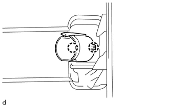
14. REMOVE CENTER POWER OUTLET SOCKET COVER
|
(a) Detach the 2 claws to remove the center power outlet socket cover. HINT: Use the same procedure as for the other sides. |
|
 Installation
INSTALLATION
PROCEDURE
1. INSTALL CENTER POWER OUTLET SOCKET COVER
(a) Attach the 2 claws to install the center power outlet socket cover.
HINT:
Use the same procedure as for the other sides.
2. ...
 Inverter Main Switch
Components
COMPONENTS
ILLUSTRATION
Installation
INSTALLATION
PROCEDURE
1. INSTALL MAIN SWITCH ASSEMBLY
(a) Attach the 2 claws to install the main switch.
2. INSTALL LOWER INSTRUMENT PANE ...
Other materials about Toyota 4Runner:
Window Glass Antenna Wire
On-vehicle Inspection
ON-VEHICLE INSPECTION
PROCEDURE
1. INSPECT WINDOW GLASS ANTENNA WIRE
(a) Check for continuity of the window glass antenna wire.
Text in Illustration
*a
Tester Probe
...
Open in Motor LH Circuit (22,24)
DESCRIPTION
When there is an open in the side auto step motor circuit, the side auto step
controller ECU assembly does not operate the automatic running board.
DTC No.
Detection Condition
Trouble Area
22
...

0.0146