Toyota 4Runner: Key Reminder Buzzer does not Sound
DESCRIPTION
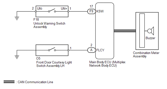
The key reminder warning buzzer sounds when the driver side door is opened while the ignition switch is ACC or off and the key is in the ignition key cylinder. The key reminder warning buzzer is activated when the main body ECU (multiplex network body ECU) sends an unlock warning switch signal and front door courtesy light switch LH signal to the combination meter.
WIRING DIAGRAM
CAUTION / NOTICE / HINT
HINT:
Since the key reminder warning system has functions that use CAN communication, first confirm that there is no malfunction in the communication system by inspecting CAN communication in accordance with the "How to Proceed with Troubleshooting" procedures. Then, conduct the following inspection procedure.
PROCEDURE
|
1. |
READ VALUE USING TECHSTREAM (FRONT DOOR COURTESY LIGHT SWITCH) |
(a) Check the Data List for proper functioning of the front door courtesy light
switch (See page .gif) ).
).
Main Body
|
Tester Display |
Measurement Item/Range |
Normal Condition |
Diagnostic Note |
|---|---|---|---|
|
FL Door Courtesy |
Front door courtesy light switch LH signal / ON or OFF |
ON: Front door LH closed OFF: Front door LH open |
- |
OK:
On tester screen, each item changes between ON and OFF according to above chart.
| NG | .gif) |
GO TO LIGHTING SYSTEM (INT) |
|
.gif)
|
2. |
READ VALUE USING TECHSTREAM (UNLOCK WARNING SWITCH) |
(a) Check the Data List for proper functioning of the unlock warning switch (See
page ).
Main Body
|
Tester Display |
Measurement Item/Range |
Normal Condition |
Diagnostic Note |
|---|---|---|---|
|
Key Unlock Warning SW |
Unlock warning switch signal / ON or OFF |
ON: Key in ignition key cylinder OFF: No key in ignition key cylinder |
- |
OK:
On tester screen, each item changes between ON and OFF according to above chart.
| OK | |
REPLACE MAIN BODY ECU (MULTIPLEX NETWORK BODY ECU) |
|
|
3. |
INSPECT UNLOCK WARNING SWITCH ASSEMBLY |
(a) Remove the unlock warning switch (See page
).
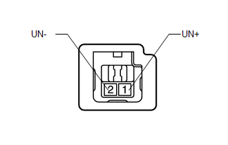
(b) Measure the resistance according to the value(s) in the table below.
Standard Resistance:
|
Tester Connection |
Switch Condition |
Specified Condition |
|---|---|---|
|
1 (UN+) - 2 (UN-) |
Not pushed |
10 kΩ or higher |
|
Pushed |
Below 1 Ω |
| NG | |
REPLACE UNLOCK WARNING SWITCH ASSEMBLY |
|
|
4. |
CHECK HARNESS AND CONNECTOR (UNLOCK WARNING SWITCH ASSEMBLY - MAIN BODY ECU AND BODY GROUND) |
(a) Disconnect the F18 unlock warning switch connector.
(b) Disconnect the F9 main body ECU connector.
(c) Measure the resistance according to the value(s) in the table below.
Standard Resistance:
|
Tester Connection |
Condition |
Specified Condition |
|---|---|---|
|
F18-1 (UN+) - F9-17 (KSW) |
Always |
Below 1 Ω |
|
F18-2 (UN-) - Body ground |
Always |
Below 1 Ω |
|
F9-17 (KSW) - Body ground |
Always |
10 kΩ or higher |
| NG | |
REPAIR OR REPLACE HARNESS OR CONNECTOR |
|
|
5. |
CHECK COMBINATION METER ASSEMBLY (OPERATION) |
(a) Temporarily replace the combination meter assembly with a new or normally
functioning one (See page ).
(b) Check the key reminder warning system (See page
).
OK:
The key reminder warning system functions properly.
| OK | |
END (COMBINATION METER ASSEMBLY IS DEFECTIVE) |
| NG | |
REPLACE MAIN BODY ECU (MULTIPLEX NETWORK BODY ECU) |
 Data List / Active Test
DATA LIST / ACTIVE TEST
1. READ DATA LIST
HINT:
Using the Techstream to read the Data List allows the values or states of switches,
sensors, actuators and other items to be read without removing ...

Other materials about Toyota 4Runner:
Customize Parameters
CUSTOMIZE PARAMETERS
1. CUSTOMIZING FUNCTION WITH THE TECHSTREAM
HINT:
The following items can be customized.
NOTICE:
When the customer requests a change in a function, first make sure that
the function can be customized.
Record the curren ...
Removal
REMOVAL
PROCEDURE
1. REMOVE REAR NO. 1 SPOILER COVER
(a) Detach the 4 clips and remove the rear No. 1 spoiler cover.
2. REMOVE REAR SPOILER SUB-ASSEMBLY
(a) Remove the 4 grommets and 4 bolts.
...

0.0087