Toyota 4Runner: Lost Communication with Door Side Airbag Sensor RH (B1692/81,B1697/82)
DESCRIPTION
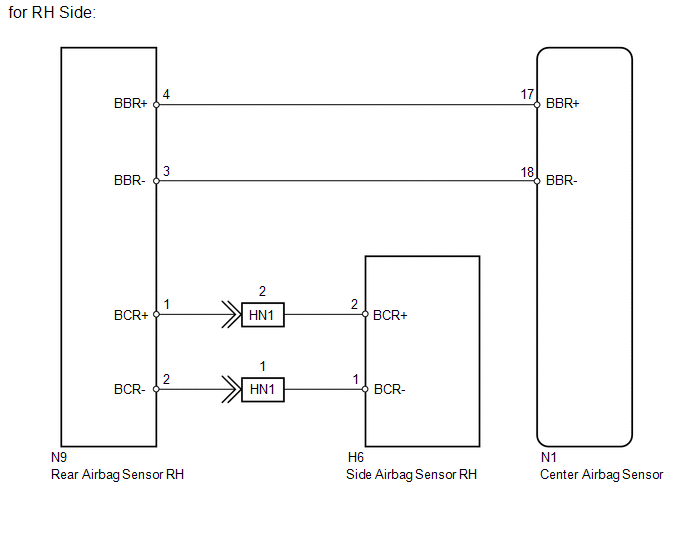
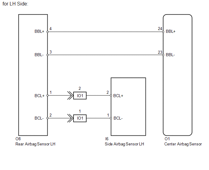
The circuit for the side collision sensor LH or RH (to determine deployment of the front seat side airbag LH or RH and curtain shield airbag LH or RH) is composed of the center airbag sensor, rear airbag sensor LH or RH and side airbag sensor LH or RH.
The rear airbag sensor LH or RH and side airbag sensor LH or RH detect impacts to the vehicle and send signals to the center airbag sensor to determine if the airbag should be deployed.
DTC B1692/81 or B1697/82 is stored when a malfunction is detected in the circuit for the side collision sensor LH or RH (to determine deployment of the front seat side airbag LH or RH and curtain shield airbag LH or RH).
|
DTC Code |
DTC Detection Condition |
Trouble Area |
|---|---|---|
|
B1692/81 |
One of the following conditions is met:
|
|
|
B1697/82 |
One of the following conditions is met:
|
|
WIRING DIAGRAM
CAUTION / NOTICE / HINT
NOTICE:
When disconnecting the cable from the negative (-) battery terminal while performing
repairs, some systems need to be initialized after the cable is reconnected (See
page .gif) ).
).
PROCEDURE
|
1. |
CHECK FOR DTC |
(a) Turn the ignition switch to ON.
(b) Clear the DTCs stored in memory (See page
).
(c) Turn the ignition switch off.
(d) Turn the ignition switch to ON, and wait for at least 60 seconds.
(e) Check for DTCs (See page ).
Result
|
Result |
Proceed to |
|---|---|
|
DTC B1692 and B1697 are not output |
A |
|
DTC B1697 is output |
B |
|
DTC B1692 is output |
C |
HINT:
Codes other than DTC B1692 and B1697 may be output at this time, but they are not related to this check.
| A | .gif) |
USE SIMULATION METHOD TO CHECK |
| B | |
GO TO STEP 8 |
|
.gif)
|
2. |
CHECK CONNECTION OF CONNECTORS |
(a) Turn the ignition switch off.
(b) Disconnect the cable from the negative (-) battery terminal, and wait for at least 90 seconds.
(c) Check that the connectors are properly connected to the center airbag sensor, rear airbag sensor RH and side airbag sensor RH.
OK:
The connectors are properly connected.
| NG | |
CONNECT CONNECTORS PROPERLY |
|
|
3. |
CHECK CONNECTORS |
(a) Disconnect the connectors from the center airbag sensor, rear airbag sensor RH and side airbag sensor RH.
|
(b) Check that the connectors (on the center airbag sensor side, rear airbag sensor RH side and side airbag sensor RH side) are not damaged. OK: The connectors are not deformed or damaged. Text in Illustration
|
|
| NG | |
REPLACE HARNESS AND CONNECTOR |
|
|
4. |
CHECK REAR AIRBAG SENSOR RH |
|
(a) Connect the connectors to the center airbag sensor and side airbag sensor RH. |
|
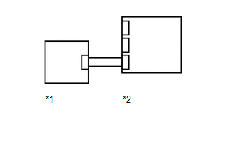
(b) Interchange the rear airbag sensor LH with RH and connect the connectors to them.
(c) Connect the cable to the negative (-) battery terminal, and wait for at least 2 seconds.
(d) Turn the ignition switch to ON, and wait for at least 60 seconds.
(e) Clear the DTCs stored in memory (See page
).
(f) Turn the ignition switch off.
(g) Turn the ignition switch to ON, and wait for at least 60 seconds.
(h) Check for DTCs (See page ).
Result
|
Result |
Proceed to |
|---|---|
|
DTC B1692 and B1697 are not output |
A |
|
DTC B1697 is output |
B |
|
DTC B1692 is output |
C |
HINT:
Codes other than DTC B1692 and B1697 may be output at this time, but they are not related to this check.
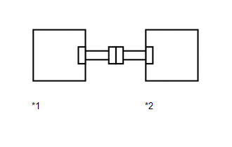
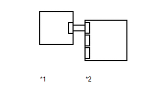
Text in Illustration|
*1 |
Rear Airbag Sensor LH |
|
*2 |
Center Airbag Sensor |
(i) Turn the ignition switch off.
(j) Disconnect the cable from the negative (-) battery terminal, and wait for at least 90 seconds.
(k) Return the rear airbag sensor RH and LH to their original positions and connect the connectors to them.
| A | |
USE SIMULATION METHOD TO CHECK |
| B | |
REPLACE REAR AIRBAG SENSOR RH |
|
|
5. |
CHECK SIDE AIRBAG SENSOR RH CIRCUIT |
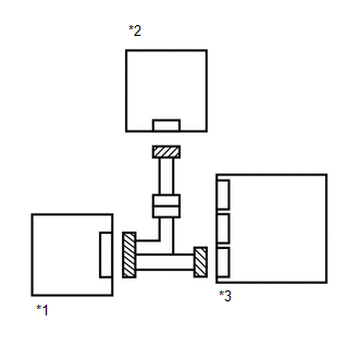
(a) Disconnect the connectors from the side airbag sensor RH and rear airbag sensor RH.
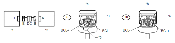
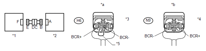 Text in Illustration
|
*1 |
Side Airbag Sensor RH |
*2 |
Rear Airbag Sensor RH |
|
*3 |
Connector E |
*4 |
Connector B |
|
*5 |
Service Wire |
- |
- |
|
*a |
Rear view of wire harness connector (to Side Airbag Sensor RH) |
*b |
Rear view of wire harness connector (to Rear Airbag Sensor RH) |
(b) Connect the cable to the negative (-) battery terminal, and wait for at least 2 seconds.
(c) Measure the voltage according to the value(s) in the table below.
Standard Voltage:
|
Tester Connection |
Switch Condition |
Specified Condition |
|---|---|---|
|
N9-1 (BCR+) - Body ground |
Ignition switch ON |
Below 1 V |
|
N9-2 (BCR-) - Body ground |
Ignition switch ON |
Below 1 V |
(d) Turn the ignition switch off.
(e) Disconnect the cable from the negative (-) battery terminal, and wait for at least 90 seconds.
(f) Using a service wire, connect terminals 2 (BCR+) and 1 (BCR-) of connector E.
NOTICE:
Do not forcibly insert the service wire into the terminals of the connector when connecting a service wire.
(g) Measure the resistance according to the value(s) in the table below.
Standard Resistance:
|
Tester Connection |
Condition |
Specified Condition |
|---|---|---|
|
N9-1 (BCR+) - N9-2 (BCR-) |
Always |
Below 1 Ω |
(h) Disconnect the service wire from connector E.
(i) Measure the resistance according to the value(s) in the table below.
Standard Resistance:
|
Tester Connection |
Condition |
Specified Condition |
|---|---|---|
|
N9-1 (BCR+) - N9-2 (BCR-) |
Always |
1 MΩ or higher |
|
N9-1 (BCR+) - Body ground |
Always |
1 MΩ or higher |
|
N9-2 (BCR-) - Body ground |
Always |
1 MΩ or higher |
| NG | |
GO TO STEP 7 |
|
|
6. |
CHECK SIDE AIRBAG SENSOR RH |
|
(a) Connect the connector to the rear airbag sensor RH. |
|
(b) Interchange the side airbag sensor LH with RH and connect the connectors to them.
(c) Connect the cable to the negative (-) battery terminal, and wait for at least 2 seconds.
(d) Turn the ignition switch to ON, and wait for at least 60 seconds.
(e) Clear the DTCs stored in memory (See page
).
(f) Turn the ignition switch off.
(g) Turn the ignition switch to ON, and wait for at least 60 seconds.
(h) Check for DTCs (See page ).
Result
|
Result |
Proceed to |
|---|---|
|
DTC B1692 and B1697 are not output |
A |
|
DTC B1697 is output |
B |
|
DTC B1692 is output |
C |
HINT:
Codes other than DTC B1692 and B1697 may be output at this time, but they are not related to this check.
Text in Illustration|
*1 |
Side Airbag Sensor LH |
|
*2 |
Rear Airbag Sensor RH |
(i) Turn the ignition switch off.
(j) Disconnect the cable from the negative (-) battery terminal, and wait for at least 90 seconds.
(k) Return the side airbag sensor RH and LH to their original positions and connect the connectors to them.
| C | |
REPLACE CENTER AIRBAG SENSOR ASSEMBLY |
| A | |
USE SIMULATION METHOD TO CHECK |
| B | |
REPLACE SIDE AIRBAG SENSOR ASSEMBLY RH |
|
7. |
CHECK FLOOR WIRE (REAR AIRBAG SENSOR RH - FRONT DOOR WIRE RH) |
(a) Disconnect the floor wire connector from the front door wire RH.
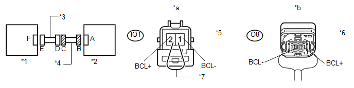
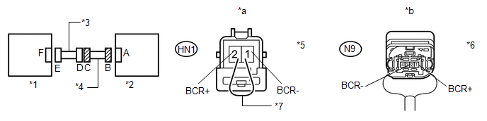 Text in Illustration
|
*1 |
Side Airbag Sensor RH |
*2 |
Rear Airbag Sensor RH |
|
*3 |
Front Door Wire RH |
*4 |
Floor Wire |
|
*5 |
Connector C |
*6 |
Connector B |
|
*7 |
Service Wire |
- |
- |
|
*a |
Front view of wire harness connector (to Front Door Wire RH) |
*b |
Rear view of wire harness connector (to Rear Airbag Sensor RH) |
(b) Connect the cable to the negative (-) battery terminal, and wait for at least 2 seconds.
(c) Measure the voltage according to the value(s) in the table below.
Standard Voltage:
|
Tester Connection |
Switch Condition |
Specified Condition |
|---|---|---|
|
N9-1 (BCR+) - Body ground |
Ignition switch ON |
Below 1 V |
|
N9-2 (BCR-) - Body ground |
Ignition switch ON |
Below 1 V |
(d) Turn the ignition switch off.
(e) Disconnect the cable from the negative (-) battery terminal, and wait for at least 90 seconds.
(f) Using a service wire, connect terminals 2 (BCR+) and 1 (BCR-) of connector C.
NOTICE:
Do not forcibly insert the service wire into the terminals of the connector when connecting a service wire.
(g) Measure the resistance according to the value(s) in the table below.
Standard Resistance:
|
Tester Connection |
Condition |
Specified Condition |
|---|---|---|
|
N9-1 (BCR+) - N9-2 (BCR-) |
Always |
Below 1 Ω |
(h) Disconnect the service wire from connector C.
(i) Measure the resistance according to the value(s) in the table below.
Standard Resistance:
|
Tester Connection |
Condition |
Specified Condition |
|---|---|---|
|
N9-1 (BCR+) - N9-2 (BCR-) |
Always |
1 MΩ or higher |
|
N9-1 (BCR+) - Body ground |
Always |
1 MΩ or higher |
|
N9-2 (BCR-) - Body ground |
Always |
1 MΩ or higher |
| OK | |
REPLACE FRONT DOOR WIRE RH |
| NG | |
REPLACE FLOOR WIRE |
|
8. |
CHECK CONNECTION OF CONNECTORS |
(a) Turn the ignition switch off.
(b) Disconnect the cable from the negative (-) battery terminal, and wait for at least 90 seconds.
(c) Check that the connectors are properly connected to the center airbag sensor, rear airbag sensor LH and side airbag sensor LH.
OK:
The connectors are properly connected.
| NG | |
CONNECT CONNECTORS PROPERLY |
|
|
9. |
CHECK CONNECTORS |
(a) Disconnect the connectors from the center airbag sensor, rear airbag sensor LH and side airbag sensor LH.
|
(b) Check that the connectors (on the center airbag sensor side, rear airbag sensor LH side and side airbag sensor LH side) are not damaged. OK: The connectors are not deformed or damaged. Text in Illustration
|
|
| NG | |
REPLACE HARNESS AND CONNECTOR |
|
|
10. |
CHECK REAR AIRBAG SENSOR LH |
|
(a) Connect the connector to the center airbag sensor and side airbag sensor LH. |
|
(b) Interchange the rear airbag sensor LH with RH and connect the connectors to them.
(c) Connect the cable to the negative (-) battery terminal, and wait for at least 2 seconds.
(d) Turn the ignition switch to ON, and wait for at least 60 seconds.
(e) Clear the DTCs stored in memory (See page
).
(f) Turn the ignition switch off.
(g) Turn the ignition switch to ON, and wait for at least 60 seconds.
(h) Check for DTCs (See page ).
Result
|
Result |
Proceed to |
|---|---|
|
DTC B1692 and B1697 are not output |
A |
|
DTC B1692 is output |
B |
|
DTC B1697 is output |
C |
HINT:
Codes other than DTC B1692 and B1697 may be output at this time, but they are not related to this check.
Text in Illustration|
*1 |
Rear Airbag Sensor RH |
|
*2 |
Center Airbag Sensor |
(i) Turn the ignition switch off.
(j) Disconnect the cable from the negative (-) battery terminal, and wait for at least 90 seconds.
(k) Return the rear airbag sensor RH and LH to their original positions and connect the connectors to them.
| A | |
USE SIMULATION METHOD TO CHECK |
| B | |
REPLACE REAR AIRBAG SENSOR LH |
|
|
11. |
CHECK SIDE AIRBAG SENSOR LH CIRCUIT |
(a) Disconnect the connectors from the rear airbag sensor LH and side airbag sensor LH.
 Text in Illustration
|
*1 |
Side Airbag Sensor LH |
*2 |
Rear Airbag Sensor LH |
|
*3 |
Connector E |
*4 |
Connector B |
|
*5 |
Service Wire |
- |
- |
|
*a |
Rear view of wire harness connector (to Side Airbag Sensor LH) |
*b |
Rear view of wire harness connector (to Rear Airbag Sensor LH) |
(b) Connect the cable to the negative (-) battery terminal, and wait for at least 2 seconds.
(c) Measure the voltage according to the value(s) in the table below.
Standard Voltage:
|
Tester Connection |
Switch Condition |
Specified Condition |
|---|---|---|
|
O8-1 (BCL+) - Body ground |
Ignition switch ON |
Below 1 V |
|
O8-2 (BCL-) - Body ground |
Ignition switch ON |
Below 1 V |
(d) Turn the ignition switch off.
(e) Disconnect the cable from the negative (-) battery terminal, and wait for at least 90 seconds.
(f) Using a service wire, connect terminals 2 (BCL+) and 1 (BCL-) of connector E.
NOTICE:
Do not forcibly insert the service wire into the terminals of the connector when connecting a service wire.
(g) Measure the resistance according to the value(s) in the table below.
Standard Resistance:
|
Tester Connection |
Condition |
Specified Condition |
|---|---|---|
|
O8-1 (BCL+) - O8-2 (BCL-) |
Always |
Below 1 Ω |
(h) Disconnect the service wire from connector E.
(i) Measure the resistance according to the value(s) in the table below.
Standard Resistance:
|
Tester Connection |
Condition |
Specified Condition |
|---|---|---|
|
O8-1 (BCL+) - O8-2 (BCL-) |
Always |
1 MΩ or higher |
|
O8-1 (BCL+) - Body ground |
Always |
1 MΩ or higher |
|
O8-2 (BCL-) - Body ground |
Always |
1 MΩ or higher |
| NG | |
GO TO STEP 13 |
|
|
12. |
CHECK SIDE AIRBAG SENSOR LH |
|
(a) Connect the connector to the rear airbag sensor LH. |
|
(b) Interchange the side airbag sensor LH with RH and connect the connectors to them.
(c) Connect the cable to the negative (-) battery terminal, and wait for at least 2 seconds.
(d) Turn the ignition switch to ON, and wait for at least 60 seconds.
(e) Clear the DTCs stored in memory (See page
).
(f) Turn the ignition switch off.
(g) Turn the ignition switch to ON, and wait for at least 60 seconds.
(h) Check for DTCs (See page ).
Result
|
Result |
Proceed to |
|---|---|
|
DTC B1692 and B1697 are not output |
A |
|
DTC B1692 is output |
B |
|
DTC B1697 is output |
C |
HINT:
Codes other than DTC B1692 and B1697 may be output at this time, but they are not related to this check.
Text in Illustration|
*1 |
Side Airbag Sensor RH |
|
*2 |
Rear Airbag Sensor LH |
(i) Turn the ignition switch off.
(j) Disconnect the cable from the negative (-) battery terminal, and wait for at least 90 seconds.
(k) Return the side airbag sensor RH and LH to their original positions and connect the connectors to them.
| C | |
REPLACE CENTER AIRBAG SENSOR ASSEMBLY |
| A | |
USE SIMULATION METHOD TO CHECK |
| B | |
REPLACE SIDE AIRBAG SENSOR ASSEMBLY LH |
|
13. |
CHECK NO. 2 FLOOR WIRE (REAR AIRBAG SENSOR LH - FRONT DOOR WIRE LH) |
(a) Disconnect the No. 2 floor wire connector from the front door wire LH.
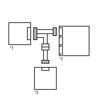
 Text in Illustration
|
*1 |
Side Airbag Sensor LH |
*2 |
Rear Airbag Sensor LH |
|
*3 |
Front Door Wire LH |
*4 |
No. 2 Floor Wire |
|
*5 |
Connector C |
*6 |
Connector B |
|
*7 |
Service Wire |
- |
- |
|
*a |
Front view of wire harness connector (to Front Door Wire LH) |
*b |
Rear view of wire harness connector (to Rear Airbag Sensor LH) |
(b) Connect the cable to the negative (-) battery terminal, and wait for at least 2 seconds.
(c) Measure the voltage according to the value(s) in the table below.
Standard Voltage:
|
Tester Connection |
Switch Condition |
Specified Condition |
|---|---|---|
|
O8-1 (BCL+) - Body ground |
Ignition switch ON |
Below 1 V |
|
O8-2 (BCL-) - Body ground |
Ignition switch ON |
Below 1 V |
(d) Turn the ignition switch off.
(e) Disconnect the cable from the negative (-) battery terminal, and wait for at least 90 seconds.
(f) Using a service wire, connect terminals 2 (BCL+) and 1 (BCL-) of connector C.
NOTICE:
Do not forcibly insert the service wire into the terminals of the connector when connecting a service wire.
(g) Measure the resistance according to the value(s) in the table below.
Standard Resistance:
|
Tester Connection |
Condition |
Specified Condition |
|---|---|---|
|
O8-1 (BCL+) - O8-2 (BCL-) |
Always |
Below 1 Ω |
(h) Disconnect the service wire from connector C.
(i) Measure the resistance according to the value(s) in the table below.
Standard Resistance:
|
Tester Connection |
Condition |
Specified Condition |
|---|---|---|
|
O8-1 (BCL+) - O8-2 (BCL-) |
Always |
1 MΩ or higher |
|
O8-1 (BCL+) - Body ground |
Always |
1 MΩ or higher |
|
O8-2 (BCL-) - Body ground |
Always |
1 MΩ or higher |
| OK | |
REPLACE FRONT DOOR WIRE LH |
| NG | |
REPLACE NO. 2 FLOOR WIRE |
 Data List / Active Test
DATA LIST / ACTIVE TEST
1. READ DATA LIST
HINT:
Using the Techstream to read the Data List allows the values or states of switches,
sensors, actuators and other items to be read without removing ...
 Diagnostic Trouble Code Chart
DIAGNOSTIC TROUBLE CODE CHART
If a trouble code is output during the DTC check, inspect the trouble
areas listed for that code. For details of the code, refer to the "See page"
...
Other materials about Toyota 4Runner:
Light Sensor Circuit Malfunction (B1244)
DESCRIPTION
The automatic light control sensor detects ambient light, converts it into an
electrical signal, and outputs it to the main body ECU. The main body ECU turns
on or off the headlights and taillights according to the signal.
DTC Code ...
Theft Deterrent System Presence Detection (B279C)
DESCRIPTION
If an ECM that is incompatible with the engine immobiliser system is installed,
the ECM stores this DTC.
DTC Code
DTC Detection Condition
Trouble Area
B279C
An ECM for vehicles withou ...
0.0069