Toyota 4Runner: Light Sensor Circuit Malfunction (B1244)
DESCRIPTION
The automatic light control sensor detects ambient light, converts it into an electrical signal, and outputs it to the main body ECU. The main body ECU turns on or off the headlights and taillights according to the signal.
|
DTC Code |
DTC Detection Condition |
Trouble Area |
|---|---|---|
|
B1244 |
|
|
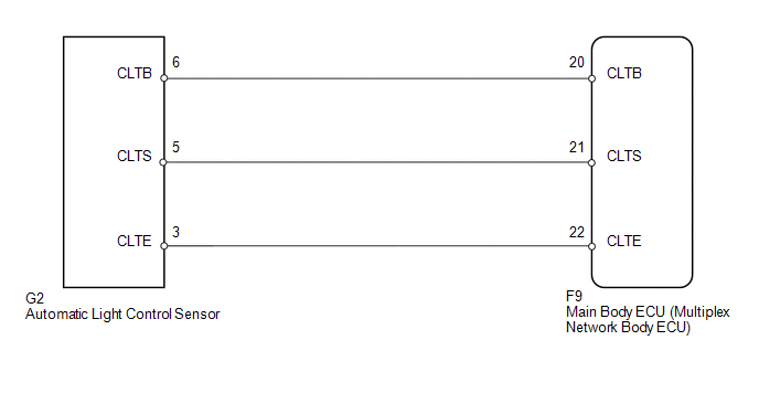
WIRING DIAGRAM
PROCEDURE
|
1. |
CHECK FOR DTC |
(a) Clear the DTCs (See page .gif) ).
).
(b) Check for DTCs (See page ).
OK:
DTC B1244 output does not occur.
| OK | .gif) |
USE SIMULATION METHOD TO CHECK |
|
.gif)
|
2. |
READ VALUE USING TECHSTREAM (AUTOMATIC LIGHT CONTROL SENSOR) |
(a) Using the Techstream, read the Data List (See page
).
Main Body
|
Tester Display |
Measurement Item/Range |
Normal Condition |
Diagnostic Note |
|---|---|---|---|
|
Illumination Rate Info |
Illumination rate information / 0 ms. to 99.99 ms. |
Value is output according to ambient light levels |
- |
OK:
Normal condition listed above is displayed.
| OK | |
REPLACE MAIN BODY ECU (MULTIPLEX NETWORK BODY ECU) |
|
|
3. |
CHECK HARNESS AND CONNECTOR (MAIN BODY ECU - AUTOMATIC LIGHT CONTROL SENSOR) |
(a) Disconnect the F9 main body ECU connector.
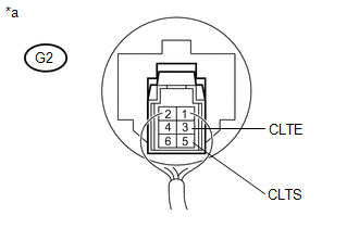
(b) Disconnect the G2 automatic light control sensor connector.
(c) Measure the resistance according to the value(s) in the table below.
Standard Resistance:
|
Tester Connection |
Condition |
Specified Condition |
|---|---|---|
|
F9-22 (CLTE) - G2-3 (CLTE) |
Always |
Below 1 Ω |
|
F9-21 (CLTS) - G2-5 (CLTS) |
Always |
Below 1 Ω |
|
F9-20 (CLTB) - G2-6 (CLTB) |
Always |
Below 1 Ω |
|
F9-22 (CLTE) - Body ground |
Always |
10 kΩ or higher |
|
F9-21 (CLTS) - Body ground |
Always |
10 kΩ or higher |
|
F9-20 (CLTB) - Body ground |
Always |
10 kΩ or higher |
| NG | |
REPAIR OR REPLACE HARNESS OR CONNECTOR |
|
|
4. |
CHECK MAIN BODY ECU (MULTIPLEX NETWORK BODY ECU) |
|
(a) Reconnect the F9 main body ECU connector. |
|
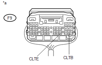
(b) Measure the voltage according to the value(s) in the table below.
Standard Voltage:
|
Tester Connection |
Switch Condition |
Specified Condition |
|---|---|---|
|
F9-20 (CLTB) - F9-22 (CLTE) |
Ignition switch off |
Below 1 V |
|
Ignition switch ON |
11 to 14 V |
|
*a |
Component with harness connected (Main Body ECU) |
| NG | |
REPLACE MAIN BODY ECU (MULTIPLEX NETWORK BODY ECU) |
|
|
5. |
CHECK AUTOMATIC LIGHT CONTROL SENSOR |
|
(a) Reconnect the G2 automatic light control sensor connector. |
|
(b) Connect an oscilloscope to the automatic light control sensor connector.
|
(c) Check the waveform. OK:
HINT: If the ambient light becomes brighter, width A becomes narrower. |
|
.png)
| OK | |
REPLACE MAIN BODY ECU (MULTIPLEX NETWORK BODY ECU) |
| NG | |
REPLACE AUTOMATIC LIGHT CONTROL SENSOR |
 Diagnostic Trouble Code Chart
DIAGNOSTIC TROUBLE CODE CHART
HINT:
If a trouble code is output during the DTC check, inspect the trouble areas listed
for that code. For details of the code, refer to the "See page" bel ...
 Headlight Dimmer Switch Circuit
DESCRIPTION
The main body ECU receives the following signals:
Headlight dimmer switch tail, head, AUTO*, high or high flash signal
Front fog light switch signal
*: w/ Aut ...
Other materials about Toyota 4Runner:
Seat belts
Make sure that all occupants are wearing their seat belts before driving
the vehicle.
Correct use of the seat belts
• Extend the shoulder belt so that it comes fully over the shoulder, but does
not come into contact with the neck or slide off the sho ...
Cellular Phone Registration Failure
CAUTION / NOTICE / HINT
NOTICE:
After replacing the navigation receiver assembly of vehicles subscribed to pay-type
satellite radio broadcasts, XM radio ID registration is necessary.
HINT:
If the operation of a cellular phone or the navigation receiver a ...

0.0266