Toyota 4Runner: Lost Communication with Rear Floor Airbag Sensor RH (B1676/85,B1677/85)
DESCRIPTION
HINT:
"Rear floor airbag sensor RH" refers to the rear floor side airbag sensor.
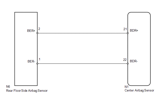
- The rear floor side airbag sensor circuit consists of the center airbag sensor and rear floor side airbag sensor.
- The rear floor side airbag sensor detects impacts to the vehicle and sends signals to the center airbag sensor to determine if the airbag should be deployed.
- DTC B1676/85 or B1677/85 is stored when a malfunction is detected in the rear floor side airbag sensor circuit.
|
DTC Code |
DTC Detection Condition |
Trouble Area |
|---|---|---|
|
B1676/85 |
One of the following conditions is met:
|
|
|
B1677/85 |
One of the following conditions is met:
|
|
WIRING DIAGRAM
CAUTION / NOTICE / HINT
NOTICE:
When disconnecting the cable from the negative (-) battery terminal while performing
repairs, some systems need to be initialized after the cable is reconnected (See
page .gif) ).
).
PROCEDURE
|
1. |
CHECK CONNECTION OF CONNECTORS |
(a) Turn the ignition switch off.
(b) Disconnect the cable from the negative (-) battery terminal, and wait for at least 90 seconds.
(c) Check that the connectors are properly connected to the center airbag sensor and rear floor side airbag sensor.
OK:
The connectors are properly connected.
| NG | .gif) |
CONNECT CONNECTORS PROPERLY |
|
.gif)
|
2. |
CHECK CONNECTORS |
(a) Disconnect the connectors from the center airbag sensor and rear floor side airbag sensor.
|
(b) Check that the connectors (on the center airbag sensor side and rear floor side airbag sensor side) are not damaged. OK: The connectors are not deformed or damaged. Text in Illustration
|
|
| NG | |
REPLACE FLOOR WIRE |
|
|
3. |
CHECK FLOOR WIRE (CENTER AIRBAG SENSOR - REAR FLOOR SIDE AIRBAG SENSOR) |
(a) Connect the cable to the negative (-) battery terminal, and wait for at least 2 seconds.
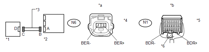 Text in Illustration
|
*1 |
Rear Floor Side Airbag Sensor |
*2 |
Center Airbag Sensor |
|
*3 |
Floor Wire |
*4 |
Connector C |
|
*5 |
Connector B |
*6 |
Service Wire |
|
*a |
Front view of wire harness connector (to Rear Floor Side Airbag Sensor) |
*b |
Rear view of wire harness connector (to Center Airbag Sensor) |
(b) Measure the voltage according to the value(s) in the table below.
Standard Voltage:
|
Tester Connection |
Switch Condition |
Specified Condition |
|---|---|---|
|
N6-2 (BER+) - Body ground |
Ignition switch ON |
Below 1 V |
|
N6-1 (BER-) - Body ground |
Ignition switch ON |
Below 1 V |
(c) Turn the ignition switch off.
(d) Disconnect the cable from the negative (-) battery terminal, and wait for at least 90 seconds.
(e) Using a service wire, connect terminals 21 (BDR+) and 22 (BDR-) of connector B.
NOTICE:
Do not forcibly insert the service wire into the terminals of the connector when connecting a service wire.
(f) Measure the resistance according to the value(s) in the table below.
Standard Resistance:
|
Tester Connection |
Condition |
Specified Condition |
|---|---|---|
|
N6-2 (BER+) - N6-1 (BER-) |
Always |
Below 1 Ω |
(g) Disconnect the service wire from connector B.
(h) Measure the resistance according to the value(s) in the table below.
Standard Resistance:
|
Tester Connection |
Condition |
Specified Condition |
|---|---|---|
|
N6-2 (BER+) - N6-1 (BER-) |
Always |
1 MΩ or higher |
|
N6-2 (BER+) - Body ground |
Always |
1 MΩ or higher |
|
N6-1 (BER-) - Body ground |
Always |
1 MΩ or higher |
| NG | |
REPLACE FLOOR WIRE |
|
|
4. |
CHECK REAR FLOOR SIDE AIRBAG SENSOR |
|
(a) Connect the connectors to the center airbag sensor. |
|
.png)
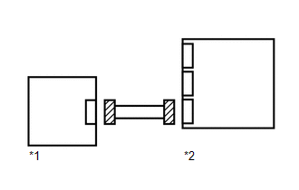
(b) Temporarily replace the rear floor side airbag sensor with a new one.
(c) Connect the cable to the negative (-) battery terminal, and wait for at least 2 seconds.
(d) Turn the ignition switch to ON, and wait for at least 60 seconds.
(e) Clear the DTCs stored in memory (See page
).
(f) Turn the ignition switch off.
(g) Turn the ignition switch to ON, and wait for at least 60 seconds.
(h) Check for DTCs (See page ).
OK:
DTC B1676 and B1677 are not output.
HINT:
Codes other than DTC B1676 and B1677 may be output at this time, but they are not related to this check.
Text in Illustration|
*1 |
Rear Floor Side Airbag Sensor |
|
*2 |
Center Airbag Sensor |
| OK | |
REPLACE REAR FLOOR SIDE AIRBAG SENSOR |
| NG | |
REPLACE CENTER AIRBAG SENSOR ASSEMBLY |
 Short in Front Passenger Side Squib 2nd Step Circuit (B1815/54-B1818/54)
DESCRIPTION
The front passenger side squib 2nd step circuit consists of the center airbag
sensor and instrument panel passenger airbag.
The circuit instructs the SRS to deploy when deployment cond ...
 Door Side Airbag Sensor RH Malfunction (B1690/15,B1695/16)
DESCRIPTION
The side airbag sensor LH or RH consists of the safing sensor, diagnostic circuit,
lateral deceleration sensor, etc.
If the center airbag sensor receives signals from the lateral decel ...
Other materials about Toyota 4Runner:
Diagnosis Circuit
DESCRIPTION
DTC output mode is set by connecting terminals TC and CG of the DLC3.
DTCs are output by the blinking of the SRS warning light.
HINT:
When each warning light continues blinking, a ground short in the wiring
of terminal TC of the DLC ...
Terminals Of Ecu
TERMINALS OF ECU
1. CHECK TIRE PRESSURE WARNING ECU
HINT:
Inspect the connector from the back side.
(a) Disconnect the F7 ECU connector.
(b) Measure the voltage according to the value(s) in the table below.
Terminal No. (Symbol)
W ...
0.0125