Toyota 4Runner: Low Pressure Malfunction in Upside of KDSS System (C1851/51,C1853/53)
DESCRIPTION
In the KDSS hydraulic circuit, the fluid is contained under pressure. If the fluid temperature is 20°C (68°F), the pressure is approximately 3.0 MPa (30.6 kgf/cm2, 435 psi).
|
DTC Code |
DTC Detection Condition |
Trouble Area |
|---|---|---|
|
C1851/51 |
The sensor output is 0.9 MPa (9.2 kgf/cm2, 130 psi) or less for 5 min. continuously with the ignition switch ON. |
|
|
C1853/53 |
The sensor output is 8.8 MPa (89.7 kgf/cm2, 1276 psi) or more for 20 sec. continuously with the ignition switch ON. |
CAUTION / NOTICE / HINT
HINT:
- When these DTCs are output, perform the hydraulic circuit inspection
first (See page
.gif) ).
). - If the DTCs cannot be cleared even after the hydraulic circuit inspection, perform the electrical circuit inspection by following the procedures below.
PROCEDURE
|
1. |
INSPECT FOR FLUID LEAK |
(a) Inspect for fluid leaks (See page ).
OK:
No fluid leaks.
| NG | .gif) |
REPAIR FLUID LEAK OR REPLACE PARTS AS NECESSARY |
|
.gif)
|
2. |
CHECK ANY OTHER DTCS OUTPUT (DTC C1812/12, C1831/31 AND/OR C1832/32) |
(a) Check if DTC C1812/12, C1831/31 and/or C1832/32 is output (See page
).
Result
|
Result |
Proceed to |
|---|---|
|
No DTC is output |
A |
|
DTC C1812/12, C1831/31 and/or C1832/32 is output |
B |
| B | |
REPAIR CIRCUITS INDICATED BY OUTPUT DTCS |
|
|
3. |
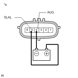
INSPECT STABILIZER CONTROL SOLENOID VALVE (CHECK IF VALVE STUCK) |
(a) Disconnect the stabilizer control with accumulator housing assembly connector.
(b) Check for an operating sound of the stabilizer control solenoid valve.
|
(1) for Upper Chamber: Connect terminal 5 (SLAL) to the positive (+) battery terminal, and terminal 4 (AUG) to the negative (-) battery terminal. OK: An operating sound (click sound) can be heard. Text in Illustration
|
|
|
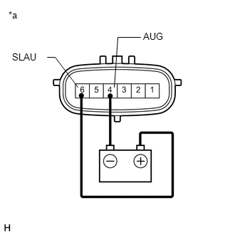
(2) for Lower Chamber: Connect terminal 6 (SLAU) to the positive (+) battery terminal, and terminal 4 (AUG) to the negative (-) battery terminal. OK: An operating sound (click sound) can be heard. Text in Illustration
|
|
| NG | |
REPLACE STABILIZER CONTROL WITH ACCUMULATOR HOUSING ASSEMBLY |
|
|
4. |
INSPECT FOR CLOGS IN HYDRAULIC CIRCUIT |
(a) Bleed air and check that the hydraulic circuit is not clogged (See page
).
OK:
Hydraulic circuit is not clogged.
| NG | |
REPAIR HYDRAULIC CIRCUIT MALFUNCTIONS OR REPLACE PARTS AS NECESSARY |
|
|
5. |
RECONFIRM DTC |
(a) Clear the DTCs (See page ).
(b) Check for DTCs (See page ).
Result
|
Result |
Proceed to |
|---|---|
|
DTC is not output |
A |
|
DTC is output |
B |
| A | |
USE SIMULATION METHOD TO CHECK |
| B | |
REPLACE STABILIZER CONTROL ECU |
 Lost Communication with ECM/PCM "A" (U0100/71,U0122/71,U0124/71,U0126/71)
DESCRIPTION
DTC Code
DTC Detection Condition
Trouble Area
U0100/71
While driving at 30 km/h (19 mph), the ECM indicates a CAN communicatio ...
 Pressure Sensor Malfunction / Upside (C1812/12)
DESCRIPTION
In the KDSS hydraulic circuit, the fluid is contained under pressure. If the
fluid temperature is 20°C (68°F), the pressure is approximately 3.0 MPa (30.6 kgf/cm2,
435 psi).
...
Other materials about Toyota 4Runner:
Under Hood
General Maintenance
GENERAL MAINTENANCE
PROCEDURE
1. GENERAL NOTES
Maintenance requirements vary depending on the country.
Check the maintenance schedule in the owner's manual supplement.
Following the maintenance schedule is mandat ...
Short to GND in Motor LH Circuit (21,23)
DESCRIPTION
When there is a short to GND in the side auto step motor circuit, the side auto
step controller ECU assembly does not operate the automatic running board.
DTC No.
Detection Condition
Trouble Area
...

0.0089