Toyota 4Runner: Luggage Room Light Circuit
DESCRIPTION
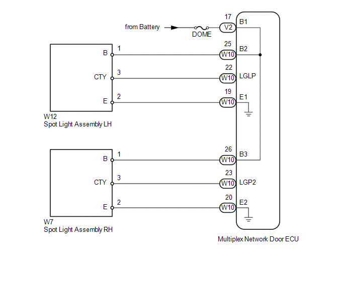
The multiplex network door ECU controls the spot light.
WIRING DIAGRAM
CAUTION / NOTICE / HINT
NOTICE:
Inspect the fuses and bulbs for circuits related to this system before performing the following inspection procedure.
PROCEDURE
|
1. |
PERFORM ACTIVE TEST USING TECHSTREAM (SPOT LIGHT) |
(a) Using the Techstream, perform the Active Test (See page
.gif) ).
).
Back Door
|
Tester Display |
Test Part |
Control Range |
Diagnostic Note |
|---|---|---|---|
|
Luggage Compartment Light |
Spot light |
ON/OFF |
- |
OK:
Spot light comes on.
| OK | .gif) |
PROCEED TO NEXT SUSPECTED AREA SHOWN IN PROBLEM SYMPTOMS TABLE |
|
.gif)
|
2. |
CHECK HARNESS AND CONNECTOR (BATTERY - MULTIPLEX NETWORK DOOR ECU) |
(a) Disconnect the V2 multiplex network door ECU connector.
(b) Measure the voltage according to the value(s) in the table below.
Standard Voltage:
|
Tester Connection |
Condition |
Specified Condition |
|---|---|---|
|
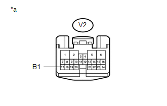
V2-17 (B1) - Body ground |
Always |
11 to 14 V |
|
*a |
Front view of wire harness connector (to Multiplex Network Door ECU) |
| NG | |
REPAIR OR REPLACE HARNESS OR CONNECTOR |
|
|
3. |
CHECK HARNESS AND CONNECTOR (SPOT LIGHT ASSEMBLY - MULTIPLEX NETWORK DOOR ECU) |
(a) Disconnect the W12 or W7 spot light connector.
(b) Disconnect the W10 multiplex network door ECU connector.
(c) Measure the resistance according to the value(s) in the table below.
Standard Resistance:
for LH
|
Tester Connection |
Condition |
Specified Condition |
|---|---|---|
|
W12-1 (B) - W10-25 (B2) |
Always |
Below 1 Ω |
|
W12-3 (CTY) - W10-22 (LGLP) |
Always |
Below 1 Ω |
|
W12-2 (E) - W10-19 (E1) |
Always |
Below 1 Ω |
|
W12-1 (B) - Body ground |
Always |
10 kΩ or higher |
|
W12-3 (CTY) - Body ground |
Always |
10 kΩ or higher |
|
W12-2 (E) - Body ground |
Always |
10 kΩ or higher |
for RH
|
Tester Connection |
Condition |
Specified Condition |
|---|---|---|
|
W7-1 (B) - W10-26 (B3) |
Always |
Below 1 Ω |
|
W7-3 (CTY) - W10-23 (LGP2) |
Always |
Below 1 Ω |
|
W7-2 (E) - W10-20 (E2) |
Always |
Below 1 Ω |
|
W7-1 (B) - Body ground |
Always |
10 kΩ or higher |
|
W7-3 (CTY) - Body ground |
Always |
10 kΩ or higher |
|
W7-2 (E) - Body ground |
Always |
10 kΩ or higher |
| OK | |
PROCEED TO NEXT SUSPECTED AREA SHOWN IN PROBLEM SYMPTOMS TABLE |
| NG | |
REPAIR OR REPLACE HARNESS OR CONNECTOR |
 Inside Handle Illumination Light Circuit
DESCRIPTION
The main body ECU (multiplex network body ECU) controls the inside handle illumination.
WIRING DIAGRAM
CAUTION / NOTICE / HINT
NOTICE:
Inspect the fuses for circuits related to this ...
 Door Mirror Foot Light Circuit
DESCRIPTION
The main body ECU controls the door mirror foot light.
WIRING DIAGRAM
CAUTION / NOTICE / HINT
NOTICE:
Inspect the fuses for circuits related to this system before performing ...
Other materials about Toyota 4Runner:
XM Tuner Malfunction (B15BA)
DESCRIPTION
These DTCs are stored when a malfunction occurs in the stereo component tuner
assembly.
DTC Code
DTC Detection Condition
Trouble Area
B15BA
When either of the conditions below is met: ...
Inspection
INSPECTION
PROCEDURE
1. INSPECT REAR NO. 1 SEAT OUTER BELT ASSEMBLY
(a) Check the ELR.
(1) When the inclination of the retractor is 15° or less, check that
the belt can be pulled from the retractor. When the inclination of the retractor
...

0.0275