Toyota 4Runner: Door Mirror Foot Light Circuit
DESCRIPTION
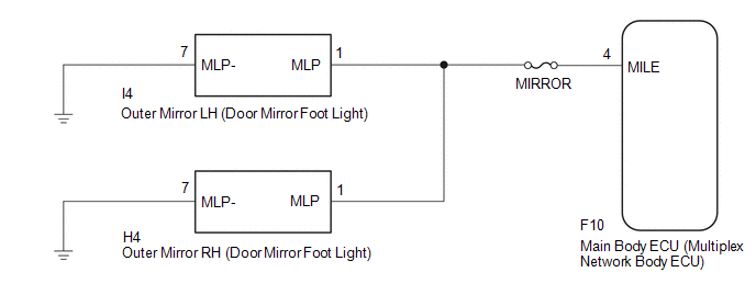
The main body ECU controls the door mirror foot light.
WIRING DIAGRAM
CAUTION / NOTICE / HINT
NOTICE:
- Inspect the fuses for circuits related to this system before performing the following procedure.
PROCEDURE
|
1. |
PERFORM ACTIVE TEST USING TECHSTREAM (DOOR MIRROR FOOT LIGHT) |
(a) Using the Techstream, perform the Active Test (See page
.gif) ).
).
Main Body
|
Tester Display |
Test Part |
Control Range |
Diagnostic Note |
|---|---|---|---|
|
Side Mirror Foot Light |
Door mirror foot light |
ON/OFF |
- |
OK:
Door mirror foot light comes on.
| OK | .gif) |
PROCEED TO NEXT SUSPECTED AREA SHOWN IN PROBLEM SYMPTOMS TABLE |
|
.gif)
|
2. |
CHECK HARNESS AND CONNECTOR (OUTER MIRROR - MAIN BODY ECU AND BODY GROUND) |
(a) Disconnect the I4 and H4 outer mirror connectors.
(b) Disconnect the F10 main body ECU connector.
(c) Measure the resistance according to the value(s) in the table below.
Standard Resistance:
for LH
|
Tester Connection |
Condition |
Specified Condition |
|---|---|---|
|
I4-1 (MLP) - F10-4 (MILE) |
Always |
Below 1 Ω |
|
I4-7 (MLP-) - Body ground |
Always |
Below 1 Ω |
|
I4-1 (MLP) - Body ground |
Always |
10 kΩ or higher |
for RH
|
Tester Connection |
Condition |
Specified Condition |
|---|---|---|
|
H4-1 (MLP) - F10-4 (MILE) |
Always |
Below 1 Ω |
|
H4-7 (MLP-) - Body ground |
Always |
Below 1 Ω |
|
H4-1 (MLP) - Body ground |
Always |
10 kΩ or higher |
| OK | |
PROCEED TO NEXT SUSPECTED AREA SHOWN IN PROBLEM SYMPTOMS TABLE |
| NG | |
REPAIR OR REPLACE HARNESS OR CONNECTOR |
 Luggage Room Light Circuit
DESCRIPTION
The multiplex network door ECU controls the spot light.
WIRING DIAGRAM
CAUTION / NOTICE / HINT
NOTICE:
Inspect the fuses and bulbs for circuits related to this system before perform ...
 Luggage Compartment Room Light
Components
COMPONENTS
ILLUSTRATION
Removal
REMOVAL
CAUTION / NOTICE / HINT
HINT:
Use the same procedure for the RH and LH sides.
The procedure listed below is for the LH side. ...
Other materials about Toyota 4Runner:
Radiator Grille
Components
COMPONENTS
ILLUSTRATION
Removal
REMOVAL
PROCEDURE
1. REMOVE UPPER RADIATOR SUPPORT SEAL
2. REMOVE FRONT BUMPER COVER
3. REMOVE FRONT BUMPER COVER (w/ Intuitive Parking Assist System)
4. REMOVE RADIATOR GRILLE
(a) ...
Accessory meter
The accessory meter presents the driver with a variety of drivingrelated
data including the current outside air temperature.
1. “MODE/ ” button
2. “SET/ ” button
3. Trip information Displays driving range and average fuel consumption
4. Outs ...

0.0256