Toyota 4Runner: Lumbar Switch
Components
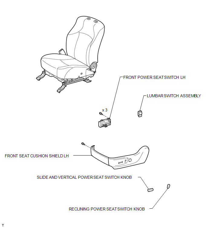
COMPONENTS
ILLUSTRATION
Inspection
INSPECTION
PROCEDURE
1. INSPECT LUMBAR SWITCH ASSEMBLY
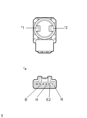
(a) Measure the resistance according to the value(s) in the table below.
Standard Resistance:
|
Tester Connection |
Switch Condition |
Specified Condition |
|---|---|---|
|
3 (H) - 5 (B) |
Hold |
Below 1 Ω |
|
1 (R) - 2 (E2) |
||
|
2 (E2) - 3 (H) |
Off |
|
|
2 (E2) - 1 (R) |
||
|
2 (E2) - 3 (H) |
Release |
|
|
1 (R) - 5 (B) |
If the result is not as specified, replace the lumbar switch.
Text in Illustration|
*1 |
Hold Switch |
|
*2 |
Release Switch |
|
*a |
Component without harness connected (Lumbar Switch) |
Removal
REMOVAL
CAUTION / NOTICE / HINT
CAUTION:
Wear protective gloves. Sharp areas on the parts may injure your hands.
PROCEDURE
1. REMOVE FRONT SEAT ASSEMBLY
(a) Remove the front seat assembly (See page .gif)
).
2. REMOVE SLIDE AND VERTICAL POWER SEAT SWITCH KNOB
3. REMOVE RECLINING POWER SEAT SWITCH KNOB
4. REMOVE FRONT SEAT CUSHION SHIELD LH
5. REMOVE FRONT POWER SEAT SWITCH LH
6. REMOVE LUMBAR SWITCH ASSEMBLY
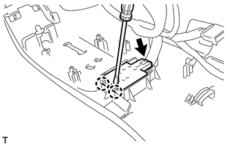
(a) Using a screwdriver, detach the 2 claws.
(b) Disconnect the lumbar switch connector and remove the lumbar switch.
Installation
INSTALLATION
CAUTION / NOTICE / HINT
CAUTION:
Wear protective gloves. Sharp areas on the parts may injure your hands.
PROCEDURE
1. INSTALL LUMBAR SWITCH ASSEMBLY
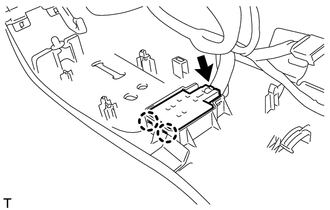
(a) Connect the lumbar switch connector.
(b) Attach the 2 claws to install the lumbar switch.
2. INSTALL FRONT POWER SEAT SWITCH LH
.gif)
3. INSTALL FRONT SEAT CUSHION SHIELD LH
4. INSTALL RECLINING POWER SEAT SWITCH KNOB
5. INSTALL SLIDE AND VERTICAL POWER SEAT SWITCH KNOB
6. INSTALL FRONT SEAT ASSEMBLY
(a) Install the front seat assembly (See page
).
 Installation
INSTALLATION
CAUTION / NOTICE / HINT
CAUTION:
Wear protective gloves. Sharp areas on the parts may injure your hands.
HINT:
Use the same procedure for the RH and LH sides.
The procedu ...

Other materials about Toyota 4Runner:
Disassembly
DISASSEMBLY
PROCEDURE
1. REMOVE RADIATOR GRILLE
2. REMOVE NO. 2 ENGINE ROOM WIRE
(a) Disconnect each connector.
(b) Detach the 9 clamps to remove the No. 2 engine room wire.
3. REMOVE NO. 1 ULTRASONIC SENSOR
4. REMOVE ULTRASONIC SENSOR CLIP
...
Data List / Active Test
DATA LIST / ACTIVE TEST
1. READ DATA LIST
HINT:
Using the Techstream to read the Data List allows values or states of switches,
sensors, actuators and other items to be read without removing any parts. This non-intrusive
inspection can be very useful be ...

0.0069