Toyota 4Runner: Microphone Amplifier
Components
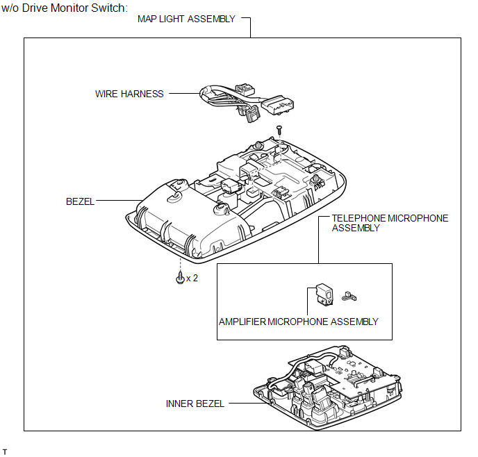
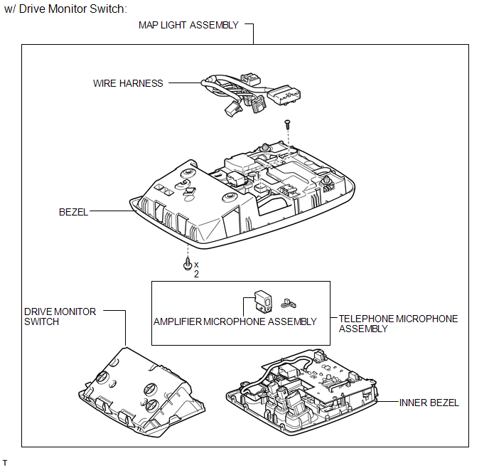
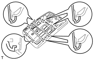
COMPONENTS
ILLUSTRATION
ILLUSTRATION
Removal
REMOVAL
PROCEDURE
1. REMOVE DRIVE MONITOR SWITCH
.gif)
2. REMOVE MAP LIGHT ASSEMBLY
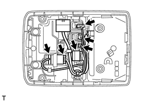
3. REMOVE TELEPHONE MICROPHONE ASSEMBLY
|
(a) Disconnect the 6 connectors. |
|
|
(b) Remove the screw. |
|
|
(c) Detach the 8 claws and remove the inner bezel. |
|
|
(d) Disconnect the connector. |
|
(e) Detach the 2 claws and remove the telephone microphone.
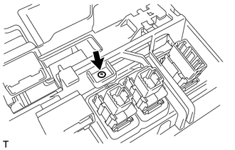
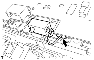
4. REMOVE AMPLIFIER MICROPHONE ASSEMBLY
|
(a) Disconnect the connector and remove the amplifier microphone. |
|
Installation
INSTALLATION
PROCEDURE
1. INSTALL AMPLIFIER MICROPHONE ASSEMBLY
(a) Connect the connector and install the amplifier microphone.
2. INSTALL TELEPHONE MICROPHONE ASSEMBLY
(a) Attach the 2 claws to install the telephone microphone.
(b) Connect the connector.
(c) Attach the 8 claws to install the inner bezel.
(d) Install the screw.
(e) Connect the 6 connectors.
3. INSTALL MAP LIGHT ASSEMBLY
.gif)
4. INSTALL DRIVE MONITOR SWITCH
 Installation
INSTALLATION
PROCEDURE
1. INSTALL STEREO COMPONENT AMPLIFIER ASSEMBLY
(a) Install the stereo component amplifier to the No. 1 speaker assembly with
box with the 3 bolts.
2. INSTALL NO. 1 SPEAKER ...
 Radio Antenna Cord
Components
COMPONENTS
ILLUSTRATION
ILLUSTRATION
ILLUSTRATION
Removal
REMOVAL
PROCEDURE
1. DISCONNECT CABLE FROM NEGATIVE BATTERY TERMINAL
CAUTION:
Wait at least 90 seconds after di ...
Other materials about Toyota 4Runner:
Fail-safe Chart
FAIL-SAFE CHART
1. FAIL-SAFE OPERATION
If there is a problem with sensor signals or hydraulic brake booster
systems, the skid control ECU prohibits power from being supplied to the
hydraulic brake booster and informs the ECM of VSC system fail ...
Problem Symptoms Table
PROBLEM SYMPTOMS TABLE
HINT:
Use the table below to help determine the cause of problem symptoms. If multiple
suspected areas are listed, the potential causes of the symptoms are listed in order
of probability in the "Suspected Area" column of ...

0.0121