Toyota 4Runner: Radio Antenna Cord
Components
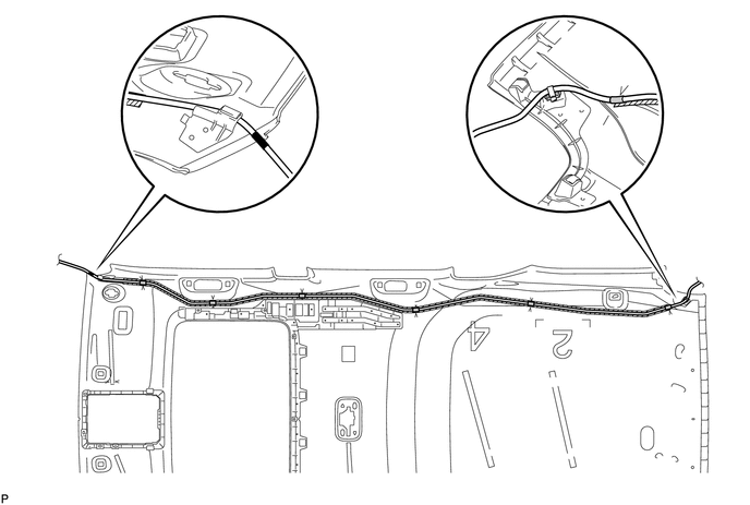
COMPONENTS
ILLUSTRATION
ILLUSTRATION
ILLUSTRATION
Removal
REMOVAL
PROCEDURE
1. DISCONNECT CABLE FROM NEGATIVE BATTERY TERMINAL
CAUTION:
Wait at least 90 seconds after disconnecting the cable from the negative (-) battery terminal to disable the SRS system.
NOTICE:
When disconnecting the cable, some systems need to be initialized after the cable
is reconnected (See page .gif) ).
).
2. REMOVE ROOF HEADLINING ASSEMBLY
(a) Remove the roof headlining assembly (See page
).
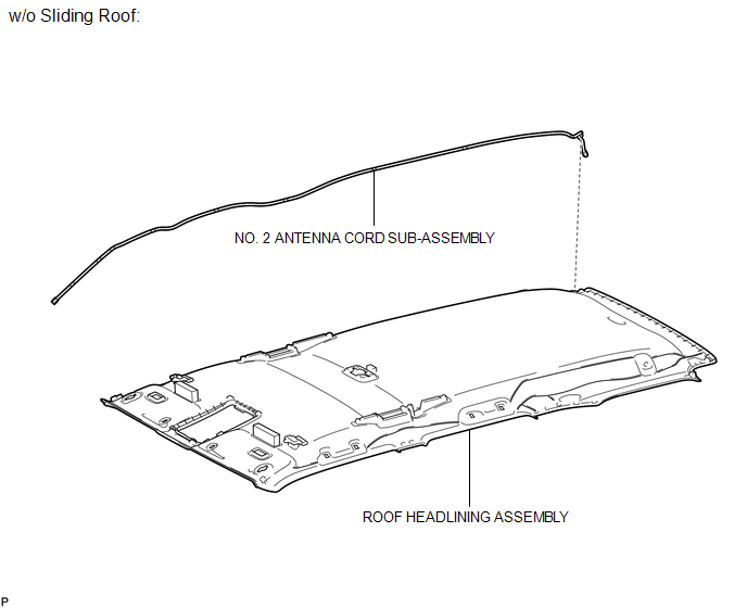
3. REMOVE NO. 2 ANTENNA CORD SUB-ASSEMBLY (w/o Sliding Roof)
(a) Detach the clamp and remove the antenna cord from the roof headlining.
(b) Remove the double-sided tape from the roof headlining.
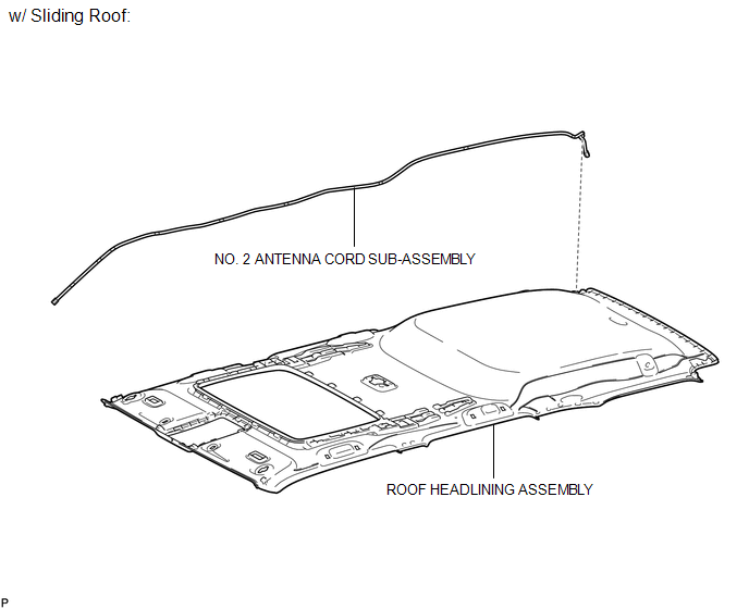
4. REMOVE NO. 2 ANTENNA CORD SUB-ASSEMBLY (w/ Sliding Roof)
(a) Detach the clamp and remove the antenna cord from the roof headlining.
(b) Remove the double-sided tape from the roof headlining.
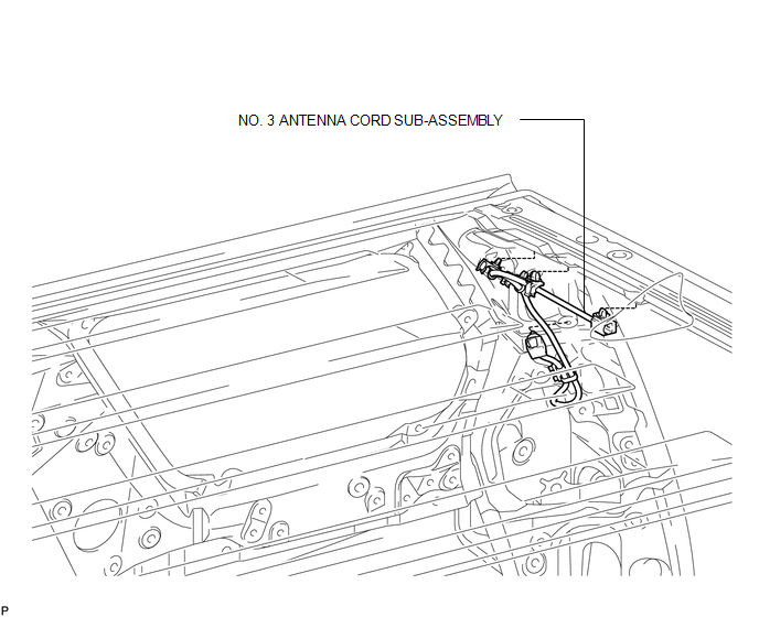
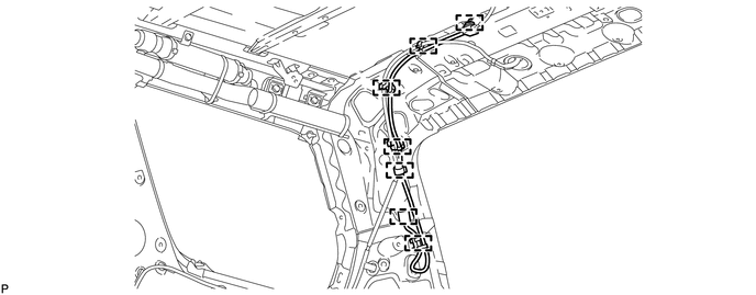
5. REMOVE NO. 3 ANTENNA CORD SUB-ASSEMBLY
(a) Disconnect the connector.
(b) Detach the 7 clamps and remove the antenna cord.
Installation
INSTALLATION
PROCEDURE
1. INSTALL NO. 3 ANTENNA CORD SUB-ASSEMBLY
(a) Attach the 7 clamps to install the antenna cord.
(b) Connect the connector.
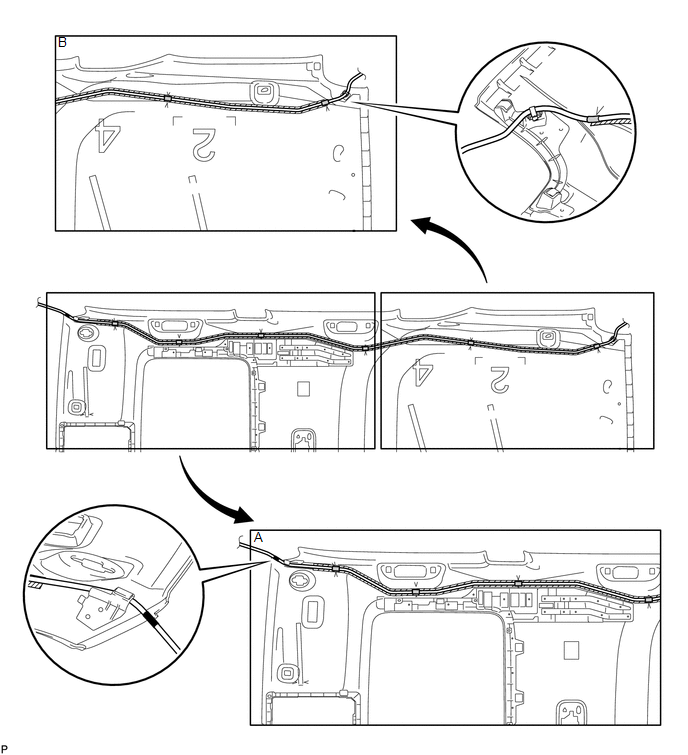
2. INSTALL NO. 2 ANTENNA CORD SUB-ASSEMBLY (w/ Sliding Roof)
(a) Apply new double-sided tape as shown in the illustration.
HINT:
Attach double-sided tape to the hatched areas shown in the illustration below.
 Text in Illustration
 |
Marking Tape |
 |
Double-sided Tape |
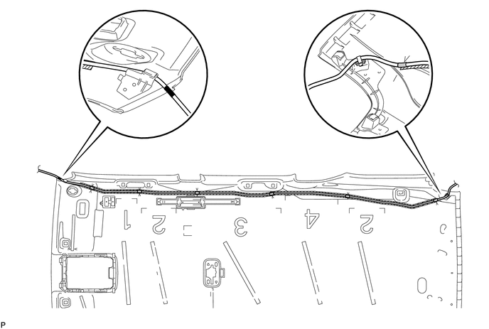
(b) Align the marking tape wound around the antenna cord with the protrusion on the roof headlining in the illustration labeled A and attach the antenna cord to the double-sided tape.
(c) Align the marking tape wound around the antenna cord with the V markings on the roof headlining at the 6 locations shown and attach the antenna cord to the double-sided tape.
(d) Attach the clamp shown in the illustration labeled B.
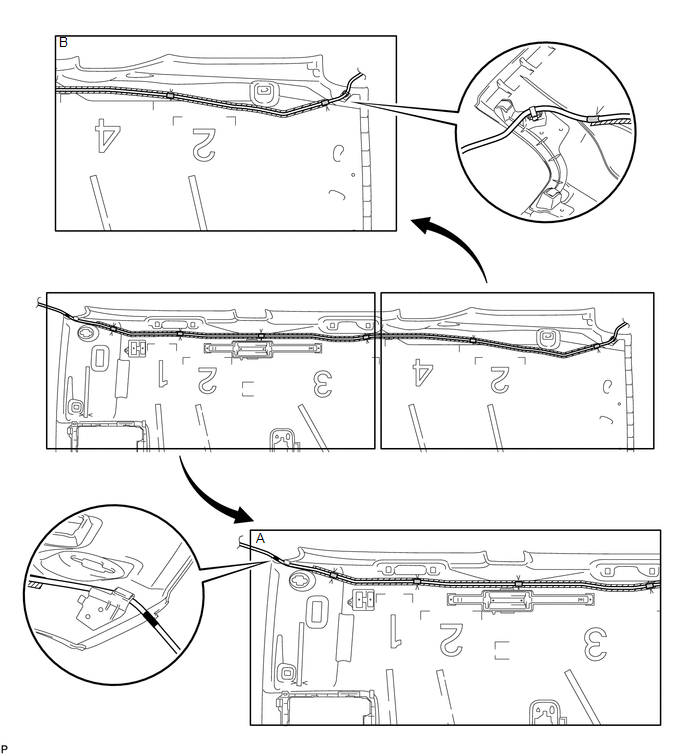
3. INSTALL NO. 2 ANTENNA CORD SUB-ASSEMBLY (w/o Sliding Roof)
(a) Apply new double-sided tape as shown in the illustration.
HINT:
Attach double-sided tape to the hatched areas shown in the illustration below.
 Text in Illustration
|
|
Marking Tape |
|
Double-sided Tape |
(b) Align the marking tape wound around the antenna cord with the protrusion on the roof headlining in the illustration labeled A and attach the antenna cord to the double-sided tape.
(c) Align the marking tape wound around the antenna cord with the V markings on the roof headlining at the 6 locations shown and attach the antenna cord to the double-sided tape.
(d) Attach the clamp shown in the illustration labeled B.
4. INSTALL ROOF HEADLINING ASSEMBLY
(a) Install the roof headlining (See page .gif) ).
).
5. CONNECT CABLE TO NEGATIVE BATTERY TERMINAL
NOTICE:
When disconnecting the cable, some systems need to be initialized after the cable
is reconnected (See page ).
6. CHECK SRS WARNING LIGHT
(a) Check the SRS warning light (See page ).
 Microphone Amplifier
Components
COMPONENTS
ILLUSTRATION
ILLUSTRATION
Removal
REMOVAL
PROCEDURE
1. REMOVE DRIVE MONITOR SWITCH
2. REMOVE MAP LIGHT ASSEMBLY
3. REMOVE TELEPHONE MICROPHONE ASSEMBLY
...
 Radio Receiver
Components
COMPONENTS
ILLUSTRATION
ILLUSTRATION
Removal
REMOVAL
PROCEDURE
1. REMOVE NO. 1 INSTRUMENT CLUSTER FINISH PANEL GARNISH
2. REMOVE NO. 2 INSTRUMENT CLUSTER FINISH PANEL GAR ...
Other materials about Toyota 4Runner:
Reassembly
REASSEMBLY
CAUTION / NOTICE / HINT
CAUTION:
Wear protective gloves. Sharp areas on the parts may injure your hands.
PROCEDURE
1. INSTALL FRONT SEAT SIDE AIRBAG ASSEMBLY
2. INSTALL SEPARATE TYPE FRONT SEATBACK COVER
(a) Using hog ring plier ...
Poor Sound Quality in All Modes (Low Volume)
PROCEDURE
1.
CHECK AUDIO SETTINGS
(a) Set treble, middle and bass to the initial values and check that the sound
is normal.
OK:
Malfunction disappears.
HINT:
Sound quality adjustment measures vary according to the type ...

0.0065