Toyota 4Runner: Microphone Circuit between Microphone and Navigation Receiver Assembly
DESCRIPTION
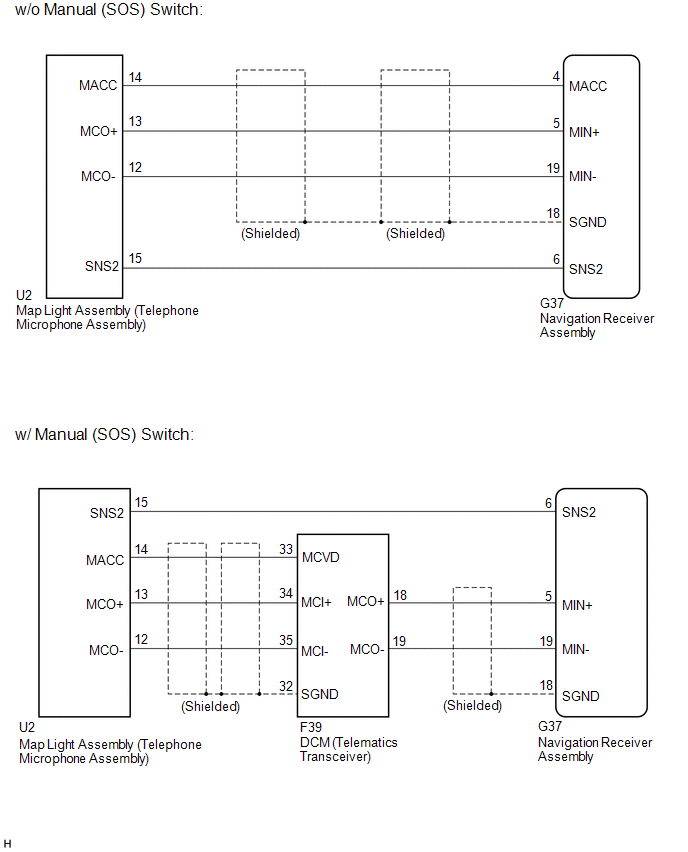
- The navigation receiver assembly and map light assembly (telephone microphone assembly) are connected to each other using the microphone connection detection signal lines.
- Using this circuit, the navigation receiver assembly sends power to the map light assembly (telephone microphone assembly), and the map light assembly (telephone microphone assembly) sends microphone signals to the navigation receiver assembly (w/o Manual (SOS) Switch).
- Using this circuit, the DCM (telematics transceiver) sends power to the map light assembly (telephone microphone assembly), and the map light assembly (telephone microphone assembly) sends microphone signals to the navigation receiver assembly via the DCM (telematics transceiver) (w/ Manual (SOS) Switch).
WIRING DIAGRAM
CAUTION / NOTICE / HINT
NOTICE:
After replacing the navigation receiver assembly of vehicles subscribed to pay-type satellite radio broadcasts, registration of the XM radio ID is necessary.
PROCEDURE
|
1. |
CONFIRM MODEL |
(a) Choose the model to be inspected.
|
Model |
Proceed to |
|---|---|
|
w/o Manual (SOS) switch |
A |
|
w/ Manual (SOS) switch |
B |
| B | .gif) |
GO TO STEP 4 |
|
.gif)
|
2. |
CHECK HARNESS AND CONNECTOR (NAVIGATION RECEIVER ASSEMBLY - MAP LIGHT ASSEMBLY (TELEPHONE MICROPHONE ASSEMBLY)) |
(a) Disconnect the G37 navigation receiver assembly connector.
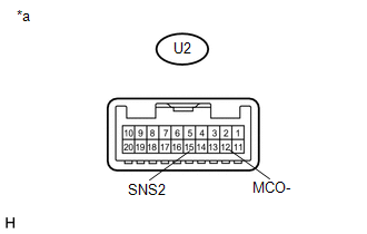
(b) Disconnect the U2 map light assembly (telephone microphone assembly) connector.
(c) Measure the resistance according to the value(s) in the table below.
Standard Resistance:
|
Tester Connection |
Condition |
Specified Condition |
|---|---|---|
|
G37-4 (MACC) - U2-14 (MACC) |
Always |
Below 1 Ω |
|
G37-5 (MIN+) - U2-13 (MCO+) |
Always |
Below 1 Ω |
|
G37-19 (MIN-) - U2-12 (MCO-) |
Always |
Below 1 Ω |
|
G37-6 (SNS2) - U2-15 (SNS2) |
Always |
Below 1 Ω |
|
G37-4 (MACC) - Body ground |
Always |
10 kΩ or higher |
|
G37-5 (MIN+) - Body ground |
Always |
10 kΩ or higher |
|
G37-19 (MIN-) - Body ground |
Always |
10 kΩ or higher |
|
G37-18 (SGND) - Body ground |
Always |
10 kΩ or higher |
|
G37-6 (SNS2) - Body ground |
Always |
10 kΩ or higher |
| NG | |
REPAIR OR REPLACE HARNESS OR CONNECTOR |
|
|
3. |
INSPECT NAVIGATION RECEIVER ASSEMBLY |
(a) Reconnect the G37 navigation receiver assembly connector.
(b) Reconnect the U2 map light assembly (telephone microphone assembly) connector.
|
(c) Measure the voltage according to the value(s) in the table below. Standard Voltage:
|
|
(d) Measure the resistance according to the value(s) in the table below.
Standard Resistance:
|
Tester Connection |
Condition |
Specified Condition |
|---|---|---|
|
G37-18 (SGND) - Body ground |
Always |
Below 1 Ω |
|
G37-19 (MIN-) - Body ground |
Always |
Below 1 Ω |
(e) Proceed to the next step based on the inspection result.
|
Result |
Proceed to |
|---|---|
|
NG |
A |
|
OK |
B |
|
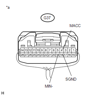
*a |
Component with harness connected (Navigation Receiver Assembly) |
| A | |
REPLACE NAVIGATION RECEIVER ASSEMBLY |
| B | |
GO TO STEP 9 |
|
4. |
CHECK HARNESS AND CONNECTOR (NAVIGATION RECEIVER ASSEMBLY - MAP LIGHT ASSEMBLY (TELEPHONE MICROPHONE ASSEMBLY)) |
(a) Disconnect the G37 navigation receiver assembly connector.
(b) Disconnect the U2 map light assembly (telephone microphone assembly) connector.
(c) Measure the resistance according to the value(s) in the table below.
Standard Resistance:
|
Tester Connection |
Condition |
Specified Condition |
|---|---|---|
|
G37-6 (SNS2) - U2-15 (SNS2) |
Always |
Below 1 Ω |
| NG | |
REPAIR OR REPLACE HARNESS OR CONNECTOR |
|
|
5. |
CHECK HARNESS AND CONNECTOR (NAVIGATION RECEIVER ASSEMBLY - DCM (TELEMATICS TRANSCEIVER)) |
(a) Disconnect the G37 navigation receiver assembly connector.
(b) Disconnect the F39 DCM (telematics transceiver) connector.
(c) Measure the resistance according to the value(s) in the table below.
Standard Resistance:
|
Tester Connection |
Condition |
Specified Condition |
|---|---|---|
|
G37-5 (MIN+) - F39-18 (MCO+) |
Always |
Below 1 Ω |
|
G37-19 (MIN-) - F39-19 (MCO-) |
Always |
Below 1 Ω |
|
G37-5 (MIN+) - Body ground |
Always |
10 kΩ or higher |
|
G37-19 (MIN-) - Body ground |
Always |
10 kΩ or higher |
|
G37-18 (SGND) - Body ground |
Always |
10 kΩ or higher |
| NG | |
REPAIR OR REPLACE HARNESS OR CONNECTOR |
|
|
6. |
CHECK HARNESS AND CONNECTOR (DCM (TELEMATICS TRANSCEIVER) - MAP LIGHT ASSEMBLY (TELEPHONE MICROPHONE ASSEMBLY)) |
(a) Disconnect the F39 DCM (telematics transceiver) connector.
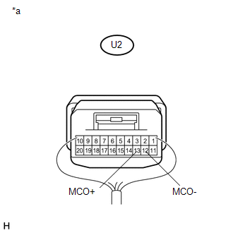
(b) Disconnect the U2 map light assembly (telephone microphone assembly) connector.
(c) Measure the resistance according to the value(s) in the table below.
Standard Resistance:
|
Tester Connection |
Condition |
Specified Condition |
|---|---|---|
|
F39-33 (MCVD) - U2-14 (MACC) |
Always |
Below 1 Ω |
|
F39-34 (MCI+) - U2-13 (MCO+) |
Always |
Below 1 Ω |
|
F39-35 (MCI-) - U2-12 (MCO-) |
Always |
Below 1 Ω |
|
F39-33 (MCVD) - Body ground |
Always |
10 kΩ or higher |
|
F39-34 (MCI+) - Body ground |
Always |
10 kΩ or higher |
|
F39-35 (MCI-) - Body ground |
Always |
10 kΩ or higher |
|
F39-32 (SGND) - Body ground |
Always |
10 kΩ or higher |
| NG | |
REPAIR OR REPLACE HARNESS OR CONNECTOR |
|
|
7. |
INSPECT NAVIGATION RECEIVER ASSEMBLY |
(a) Disconnect the F39 DCM (telematics transceiver) connector.
|
(b) Reconnect the G37 navigation receiver assembly connector. |
|
(c) Measure the resistance according to the value(s) in the table below.
Standard Resistance:
|
Tester Connection |
Condition |
Specified Condition |
|---|---|---|
|
G37-18 (SGND) - Body ground |
Always |
Below 1 Ω |
|
G37-19 (MIN-) - Body ground |
Always |
Below 1 Ω |
|
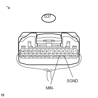
*a |
Component with harness connected (Navigation Receiver Assembly) |
| NG | |
REPLACE NAVIGATION RECEIVER ASSEMBLY |
|
|
8. |
INSPECT DCM (TELEMATICS TRANSCEIVER) |
(a) Reconnect the F39 DCM (telematics transceiver) connector.
|
(b) Measure the voltage according to the value(s) in the table below. Standard Voltage:
|
|
(c) Measure the resistance according to the value(s) in the table below.
Standard Resistance:
|
Tester Connection |
Condition |
Specified Condition |
|---|---|---|
|
F39-35 (MCI-) - Body ground |
Always |
Below 1 Ω |
|
F39-32 (SGND) - Body ground |
Always |
Below 1 Ω |
|
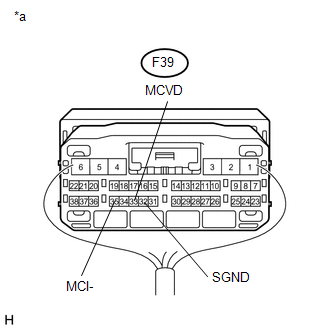
*a |
Component with harness connected (DCM (Telematics Transceiver)) |
| NG | |
REPLACE DCM (TELEMATICS TRANSCEIVER) |
|
|
9. |
INSPECT MAP LIGHT ASSEMBLY (TELEPHONE MICROPHONE ASSEMBLY) |
(a) Disconnect the U2 map light assembly (telephone microphone assembly) connector.
|
(b) Measure the resistance according to the value(s) in the table below. Standard Resistance:
|
|
| NG | |
REPLACE MAP LIGHT ASSEMBLY (TELEPHONE MICROPHONE ASSEMBLY) |
|
|
10. |
INSPECT MAP LIGHT ASSEMBLY (TELEPHONE MICROPHONE ASSEMBLY) |
(a) Reconnect the F39 DCM (telematics transceiver) connector.
|
(b) Reconnect the U2 map light assembly (telephone microphone assembly) connector. |
|
(c) Turn the ignition switch to ACC.
(d) Connect an oscilloscope to terminals 13 (MCO+) and 12 (MCO-) of the map light assembly (telephone microphone assembly) connector.
(e) Check the waveform of the telephone microphone assembly using the oscilloscope.
|
Result |
Proceed to |
|---|---|
|
A waveform synchronized with the voice input to the map light assembly (telephone microphone assembly) is output |
A |
|
A waveform synchronized with the voice input to the map light assembly (telephone microphone assembly) is not output |
B |
|
*a |
Component with harness connected (Map Light Assembly (Telephone Microphone Assembly)) |
| A | |
PROCEED TO NEXT SUSPECTED AREA SHOWN IN PROBLEM SYMPTOMS TABLE |
| B | |
REPLACE MAP LIGHT ASSEMBLY (TELEPHONE MICROPHONE ASSEMBLY) |
 Navigation Voice Circuit
DESCRIPTION
This circuit is used when the voice guidance in the navigation system is on or
an incoming cellular phone voice in the "Bluetooth" hands-free system is heard.
Using this circ ...
 Stereo Component Amplifier Power Source Circuit
DESCRIPTION
This circuit provides power to the stereo component amplifier assembly.
WIRING DIAGRAM
CAUTION / NOTICE / HINT
NOTICE:
Inspect the fuses for circuits related to this system before p ...
Other materials about Toyota 4Runner:
Problem Symptoms Table
PROBLEM SYMPTOMS TABLE
HINT:
Use the table below to help determine the cause of problem symptoms.
If multiple suspected areas are listed, the potential causes of the symptoms
are listed in order of probability in the "Suspected Area" ...
Automatic running boards
The Automatic running boards are linked to the side door operations,
extending and retracting when a side door is opened and closed. When a door is
opened or closed, the board on the same side extends or retracts.
1. Opening a door: The appropriate boar ...

0.0066