Toyota 4Runner: Motor LH Current Senser (62,63)
DESCRIPTION
When the side auto step motor current detection sensor inside the side auto step controller ECU assembly detects a current of less than 1 A when the automatic running board is operating, the side auto step controller ECU assembly does not operate the automatic running board.
|
DTC No. |
Detection Condition |
Trouble Area |
|---|---|---|
|
61 |
When the side auto step motor assembly LH is operating, there is less than 1 A of current detected in the side auto step ECU even when the hall effect pluses are input. |
|
|
62 |
When the side auto step motor assembly RH is operating, there is less than 1 A of current detected in the side auto step ECU even when the hall effect pluses are input. |
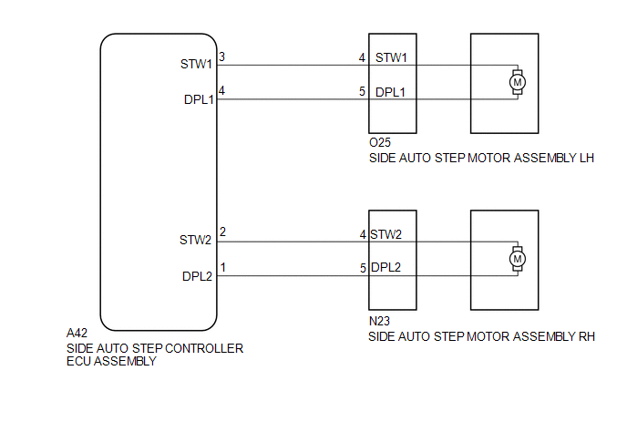
WIRING DIAGRAM
PROCEDURE
|
1. |
CHECK HARNESS AND CONNECTOR (SIDE AUTO STEP MOTOR - SIDE AUTO STEP CONTROLLER ECU) |
(a) Disconnect the O25*1 or N23*2 side auto step motor assembly connector.
- *1: for LH
- *2: for RH
(b) Disconnect the A42 side auto step controller ECU assembly connector.
(c) Measure the resistance according to the value(s) in the table below.
Standard Resistance:
for LH
|
Tester Connection |
Condition |
Specified Condition |
|---|---|---|
|
O25-4 (STW1) - A42-3 (STW1) |
Always |
Below 1 Ω |
|
O25-5 (DPL1) - A42-4 (DPL1) |
Always |
Below 1 Ω |
for RH
|
Tester Connection |
Condition |
Specified Condition |
|---|---|---|
|
N23-4 (STW2) - A42-2 (STW2) |
Always |
Below 1 Ω |
|
N23-5 (DPL2) - A42-1 (DPL1) |
Always |
Below 1 Ω |
| NG | .gif) |
REPAIR OR REPLACE HARNESS OR CONNECTOR |
|
.gif)
|
2. |
PERFORM COOL DOWN |
(a) Do not operate the automatic running board in order to cool down the side auto step motor assembly.
|
|
3. |
CHECK DTC |
(a) Recheck for DTCs and check if the same DTC is output again.
OK:
No DTCs are output.
| OK | |
END |
| NG | |
REPLACE SIDE AUTO STEP CONTROLLER ECU ASSEMBLY |
 Motor LH Over Temperature (64,65)
DESCRIPTION
When the side auto step controller ECU assembly detects the overheating in the
system, it stops the operation of the automatic running board.
DTC No.
Detection Co ...
 ECU Circuit (61)
DESCRIPTION
When the internal circuit of the side auto step controller ECU assembly malfunctions,
the side auto step controller ECU assembly halts the operation of the system.
DTC No.
...
Other materials about Toyota 4Runner:
Disassembly
DISASSEMBLY
PROCEDURE
1. REMOVE NO. 1 POWER OUTLET SOCKET ASSEMBLY
2. REMOVE NO. 1 POWER OUTLET SOCKET COVER
3. REMOVE REAR CONSOLE END PANEL
(a) Detach the 4 clips and 4 claws to remove the rear console end panel.
...
Open Circuit in IG1/IG2 Power Source Circuit (C1242)
DESCRIPTION
If there is a problem with the master cylinder solenoid (skid control ECU) power
supply circuit, the skid control ECU stores DTCs and prohibits operation under the
fail-safe function.
If the voltage supplied to the IG2 terminal is within the ...

0.0081