Toyota 4Runner: Reverse Signal Circuit
DESCRIPTION
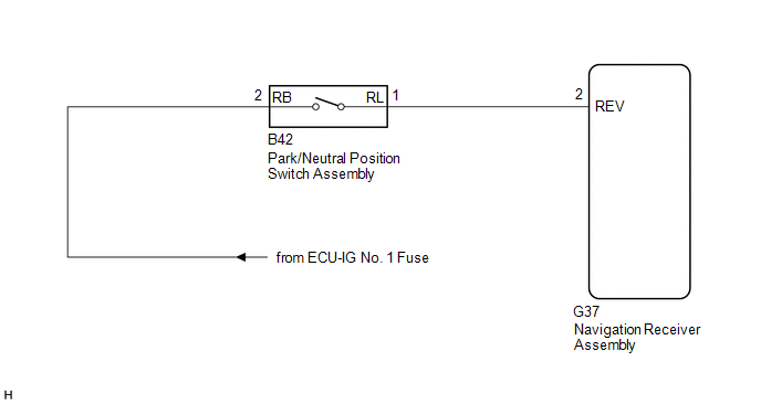
The navigation receiver assembly receives a reverse signal from the park/neutral position switch assembly.
WIRING DIAGRAM
CAUTION / NOTICE / HINT
NOTICE:
- After replacing the navigation receiver assembly of vehicles subscribed to pay-type satellite radio broadcasts, registration of the XM radio ID is necessary.
- Inspect the fuses for circuits related to this system before performing the following procedure.
PROCEDURE
|
1. |
CHECK VEHICLE SIGNAL (OPERATION CHECK) |
|
(a) Enter the "Vehicle Signal Check Mode" screen. Refer to check Vehicle
Signal in Operation Check (See page |
|
.gif) ).
).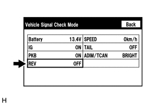
(b) Check that the display changes between ON and OFF according to the shift lever position.
OK:
|
Shift Lever Position |
Display |
|---|---|
|
R |
ON |
|
Except R |
OFF |
HINT:
This display is updated once per second. As a result, it is normal for the display to lag behind the actual shift lever position.
| OK | .gif) |
PROCEED TO NEXT SUSPECTED AREA SHOWN IN PROBLEM SYMPTOMS TABLE |
|
.gif)
|
2. |
CHECK HARNESS AND CONNECTOR (REVERSE SIGNAL) |
|
(a) Disconnect the G37 navigation receiver assembly connector. |
|
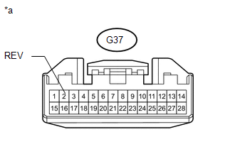
(b) Measure the voltage according to the value(s) in the table below.
Standard Voltage:
|
Tester Connection |
Condition |
Specified Condition |
|---|---|---|
|
G37-2 (REV) - Body ground |
Ignition switch ON Shift lever in R |
11 to 14 V |
|
Ignition switch ON Shift lever in any position other than R |
Below 1 V |
|
*a |
Front view of wire harness connector (to Navigation Receiver Assembly) |
| OK | |
REPLACE NAVIGATION RECEIVER ASSEMBLY |
|
|
3. |
CHECK HARNESS AND CONNECTOR (NAVIGATION RECEIVER ASSEMBLY - PARK/NEUTRAL POSITION SWITCH ASSEMBLY) |
(a) Disconnect the G37 navigation receiver assembly connector.
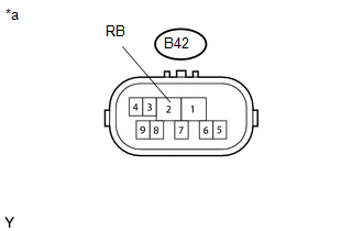
(b) Disconnect the B42 park/neutral position switch assembly connector.
(c) Measure the resistance according to the value(s) in the table below.
Standard Resistance:
|
Tester Connection |
Condition |
Specified Condition |
|---|---|---|
|
G37-2 (REV) - B42-1 (RL) |
Always |
Below 1 Ω |
|
G37-2 (REV) - Body ground |
Always |
10 kΩ or higher |
| NG | |
REPAIR OR REPLACE HARNESS OR CONNECTOR |
|
|
4. |
CHECK HARNESS AND CONNECTOR (PARK/NEUTRAL POSITION SWITCH ASSEMBLY - BATTERY) |
(a) Disconnect the B42 park/neutral position switch assembly connector.
|
(b) Measure the voltage according to the value(s) in the table below. Standard Voltage:
|
|
(c) Proceed to the next step based on the check result.
|
Result |
Proceed to |
|---|---|
|
NG |
A |
|
OK (for A750E) |
B |
|
OK (for A750F) |
C |
| A | |
REPAIR OR REPLACE HARNESS OR CONNECTOR |
| B | |
REPLACE PARK/NEUTRAL POSITION SWITCH ASSEMBLY (forA750E) |
| C | |
REPLACE PARK/NEUTRAL POSITION SWITCH ASSEMBLY (for A750F) |
 Vehicle Speed Signal Circuit between Stereo Component Amplifier and Combination
Meter
Vehicle Speed Signal Circuit between Stereo Component Amplifier and Combination
Meter
DESCRIPTION
The stereo component amplifier assembly receives a vehicle speed signal from
the combination meter assembly to control the ASL function.
HINT:
A voltage of 12 V or 5 V is outp ...
 Navigation Voice Circuit
DESCRIPTION
This circuit is used when the voice guidance in the navigation system is on or
an incoming cellular phone voice in the "Bluetooth" hands-free system is heard.
Using this circ ...
Other materials about Toyota 4Runner:
General Information
GENERAL INFORMATION
A large number of ECU controlled systems are used in the 4RUNNER. In
general, ECU controlled systems are considered to be very intricate, requiring
a high level of technical knowledge to troubleshoot. However, most problem
...
All Door Entry Lock/Unlock Functions and Wireless Functions do not Operate
DESCRIPTION
When the entry operation and wireless operation of the door lock functions do
not operate, a malfunction or wave interference may be occurring in either of the
following: 1) the signal communication line between the door control receiver and
...

0.0236