Toyota 4Runner: Multi-terrain Select Indicator Light does not Come ON
DESCRIPTION
When the ON/OFF switch of the multi-terrain select switch is turned on, multi-terrain select control is enabled and the multi-terrain select indicator light illuminates.
After selecting a road surface type using the mode selector switch of the multi-terrain select switch, the system optimizes throttle control and brake fluid pressure control for wheels that slip when accelerating, which allows the power lost when the wheels slip during acceleration to be distributed to all 4 wheels.
The slip indicator light blinks while the system is operating.
The system can operate under the following conditions:
- The vehicle stability control system is normal.
- The vehicle speed is 12 km/h (7 mph) or less.
- Crawl control is not operating.
- The selected road surface is "Mud & Sand" and the transfer is set to H4 or L4, or the selected road surface is "Loose Rock", "Mogul" or "Rock" and the transfer is set to L4.
When there is a malfunction in the multi-terrain select system, the multi-terrain select indicator light blinks.
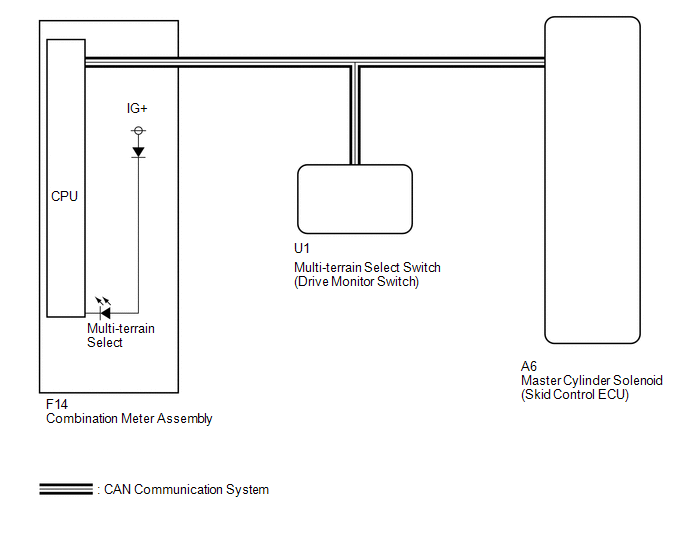
WIRING DIAGRAM
PROCEDURE
|
1. |
CHECK CAN COMMUNICATION LINE |
(a) Turn the ignition switch off.
(b) Connect the Techstream to the DLC3.
(c) Turn the ignition switch to ON.
(d) Turn the Techstream on.
(e) Select CAN Bus Check from the System Selection Menu screen and follow the
prompts on the screen to inspect the CAN bus (See page
.gif) ).
).
OK:
CAN Bus Check indicates no malfunctions in CAN communication.
| NG | .gif) |
GO TO CAN COMMUNICATION SYSTEM (HOW TO TROUBLESHOOT ECU CONTROLLED SYSTEMS) |
|
.gif)
|
2. |
CHECK FOR DTC |
(a) Check for DTCs (See page ).
Result
|
Result |
Proceed to |
|---|---|
|
DTC is not output |
A |
|
DTC is output |
B |
| B | |
REPAIR CIRCUITS INDICATED BY OUTPUT DTCS |
|
|
3. |
READ VALUE USING TECHSTREAM (OFF-ROAD GUIDANCE SWITCH (MULTI-TERRAIN SELECT SWITCH)) |
(a) Turn the ignition switch off.
(b) Connect the Techstream to the DLC3.
(c) Turn the ignition switch to ON.
(d) Turn the Techstream on.
(e) Enter the following menus: Body Electrical / D-SEAT SW / Data List.
D-SEAT SW|
Tester Display |
Measurement Item/Range |
Normal Condition |
Diagnostic Note |
|---|---|---|---|
|
Off-road Guidance Switch |
Multi-terrain select switch/ ON or OFF |
ON: Multi-terrain select switch on OFF: Multi-terrain select off |
- |
OK:
The Techstream displays ON or OFF according to multi-terrain select switch operation.
| OK | |
GO TO METER / GAUGE SYSTEM (HOW TO PROCEED WITH TROUBLESHOOTING) |
|
|
4. |
CHECK TERMINAL VOLTAGE AND RESISTANCE (IG, +B, GND) |
| OK | |
REPLACE DRIVE MONITOR SWITCH |
| NG | |
REPAIR OR REPLACE HARNESS OR CONNECTOR |
 Multi-terrain Select Indicator Light Remains ON
DESCRIPTION
Refer to Multi-terrain Select Indicator Light does not Come ON (See page
).
WIRING DIAGRAM
Refer to Multi-terrain Select Indicator Light does not Come ON (See page
).
PROCEDURE
...
 Brake Warning Light does not Come ON
DESCRIPTION
Refer to Brake Warning Light Remains ON (See page
).
WIRING DIAGRAM
Refer to Brake Warning Light Remains ON (See page
).
CAUTION / NOTICE / HINT
NOTICE:
When replacing the master ...
Other materials about Toyota 4Runner:
Data Signal Circuit between Navigation Receiver Assembly and Stereo Jack Adapter
DESCRIPTION
The No. 1 stereo jack adapter assembly sends the sound data signal or image data
signal from a USB device to the navigation receiver assembly via this circuit.
WIRING DIAGRAM
PROCEDURE
1.
CHECK HARNESS AND CONNECTOR ( ...
Sound Signal Circuit between Navigation Receiver Assembly and Stereo Component
Amplifier
DESCRIPTION
The navigation receiver assembly sends a sound signal to the stereo component
amplifier assembly via the sound signal circuit.
The sound signal that has been sent is amplified by the stereo component amplifier
assembly, and then is sent to th ...

0.0077