Toyota 4Runner: Mute Signal Circuit between Navigation Receiver Assembly and Stereo Component Amplifier
DESCRIPTION
This circuit sends a signal to the stereo component amplifier assembly to mute noise. Because of that, the noise produced by changing the sound source ceases.
If there is an open in the circuit, noise can be heard from the speakers when changing the sound source.
If there is a short in the circuit, even though the stereo component amplifier assembly is functioning normally, no sound or only an extremely faint sound can be heard.
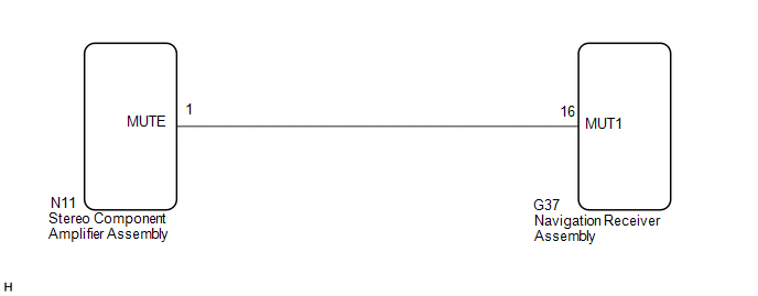
WIRING DIAGRAM
CAUTION / NOTICE / HINT
NOTICE:
After replacing the navigation receiver assembly of vehicles subscribed to pay-type satellite radio broadcasts, XM radio ID registration is necessary.
PROCEDURE
|
1. |
INSPECT STEREO COMPONENT AMPLIFIER ASSEMBLY |
|
(a) Measure the voltage according to the value(s) in the table below. Standard Voltage:
|
|
| OK | .gif) |
PROCEED TO NEXT SUSPECTED AREA SHOWN IN PROBLEM SYMPTOMS TABLE |
|
.gif)
|
2. |
CHECK HARNESS AND CONNECTOR (NAVIGATION RECEIVER ASSEMBLY - STEREO COMPONENT AMPLIFIER ASSEMBLY) |
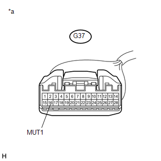
(a) Disconnect the G37 navigation receiver assembly connector.
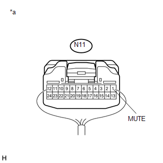
(b) Disconnect the N11 stereo component amplifier assembly connector.
(c) Measure the resistance according to the value(s) in the table below.
Standard Resistance:
|
Tester Connection |
Condition |
Specified Condition |
|---|---|---|
|
G37-16 (MUT1) - N11-1 (MUTE) |
Always |
Below 1 Ω |
|
G37-16 (MUT1) - Body ground |
Always |
10 kΩ or higher |
| NG | |
REPAIR OR REPLACE HARNESS OR CONNECTOR |
|
|
3. |
INSPECT STEREO COMPONENT AMPLIFIER ASSEMBLY (OUTPUT SIGNAL) |
(a) Reconnect the N11 stereo component amplifier assembly connector.
(b) Disconnect the G37 navigation receiver assembly connector.
|
(c) Measure the voltage according to the value(s) in the table below. Standard Voltage:
|
|
| OK | |
REPLACE NAVIGATION RECEIVER ASSEMBLY |
| NG | |
REPLACE STEREO COMPONENT AMPLIFIER ASSEMBLY |
 Data Signal Circuit between Navigation Receiver Assembly and Stereo Jack Adapter
DESCRIPTION
The No. 1 stereo jack adapter assembly sends the sound data signal or image data
signal from a USB device to the navigation receiver assembly via this circuit.
WIRING DIAGRAM
PROCED ...
 Mute Signal Circuit between Stereo Component Amplifier and Telematics Transceiver
DESCRIPTION
The DCM (telematics transceiver) sends a mute signal to the stereo component
amplifier assembly.
The stereo component amplifier assembly controls the volume according to the
mute sig ...
Other materials about Toyota 4Runner:
Rear window and outside rear view mirror defoggers
Defoggers are used to defog the rear window, and to remove raindrops, dew
and frost from the outside rear view mirrors.
Before operating the defoggers, make sure the back window is completely
closed.
Vehicles with a manual air conditioning system
Tu ...
Satellite Radio Broadcast cannot be Received
CAUTION / NOTICE / HINT
NOTICE:
Some satellite radio broadcasts require payment. A contract must be
made between a satellite radio company and the user. If the contract expires,
it will not be possible to listen to the broadcast.
After re ...

0.0076