Toyota 4Runner: Mute Signal Circuit between Stereo Component Amplifier and Telematics Transceiver
DESCRIPTION
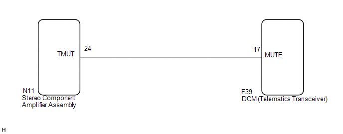
The DCM (telematics transceiver) sends a mute signal to the stereo component amplifier assembly.
The stereo component amplifier assembly controls the volume according to the mute signal from the DCM (telematics transceiver).
WIRING DIAGRAM
PROCEDURE
|
1. |
INSPECT DCM (TELEMATICS TRANSCEIVER) |
|
(a) Measure the voltage according to the value(s) in the table below. Standard Voltage:
|
|
| OK | .gif) |
PROCEED TO NEXT SUSPECTED AREA SHOWN IN PROBLEM SYMPTOMS TABLE |
|
.gif)
|
2. |
CHECK HARNESS AND CONNECTOR (STEREO COMPONENT AMPLIFIER ASSEMBLY - DCM (TELEMATICS TRANSCEIVER)) |
(a) Disconnect the N11 stereo component amplifier assembly connector.
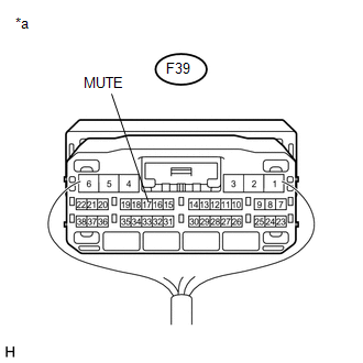
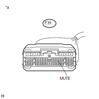
(b) Disconnect the F39 DCM (telematics transceiver) connector.
(c) Measure the resistance according to the value(s) in the table below.
Standard Resistance:
|
Tester Connection |
Condition |
Specified Condition |
|---|---|---|
|
N11-24 (TMUT) - F39-17 (MUTE) |
Always |
Below 1 Ω |
|
N11-24 (TMUT) - Body ground |
Always |
10 kΩ or higher |
| NG | |
REPAIR OR REPLACE HARNESS OR CONNECTOR |
|
|
3. |
INSPECT STEREO COMPONENT AMPLIFIER ASSEMBLY |
(a) Reconnect the N11 stereo component amplifier assembly connector.
(b) Disconnect the F39 DCM (telematics transceiver) connector.
|
(c) Measure the voltage according to the value(s) in the table below. Standard Voltage:
|
|
| OK | |
REPLACE DCM (TELEMATICS TRANSCEIVER) |
| NG | |
REPLACE STEREO COMPONENT AMPLIFIER ASSEMBLY |
 Mute Signal Circuit between Navigation Receiver Assembly and Stereo Component
Amplifier
Mute Signal Circuit between Navigation Receiver Assembly and Stereo Component
Amplifier
DESCRIPTION
This circuit sends a signal to the stereo component amplifier assembly to mute
noise. Because of that, the noise produced by changing the sound source ceases.
If there is an open in th ...
 AVC-LAN Circuit
DESCRIPTION
Each unit of the navigation system connected to the AVC-LAN (communication bus)
transfers the switch signals using the AVC-LAN.
If a short to +B or short to ground occurs in the AVC-LA ...
Other materials about Toyota 4Runner:
Installing child restraints using a seat belt (child restraint lock function
belt)
Rear facing -- Infant seat/convertible seat
Place the child restraint system on the rear seat facing the rear of the
vehicle.
Run the seat belt through the child restraint system and insert the plate
into the buckle. Make sure that the belt is not tw ...
Terminals Of Ecu
TERMINALS OF ECU
1. CHECK MAIN BODY ECU (MULTIPLEX NETWORK BODY ECU) AND DRIVER SIDE JUNCTION
BLOCK ASSEMBLY
(a) Remove the main body ECU (multiplex network body ECU) from the driver side
junction block assembly (See page ).
(b) Measure the resistanc ...

0.0088