Toyota 4Runner: Outer Rear View Mirror Glass
Components
COMPONENTS
ILLUSTRATION
Removal
REMOVAL
CAUTION / NOTICE / HINT
HINT:
- Use the same procedure for both the RH and LH sides.
- The procedure listed below is for the LH side.
PROCEDURE
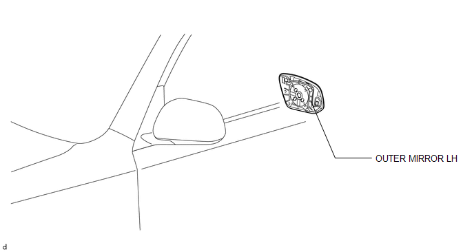
1. REMOVE OUTER MIRROR LH
(a) Put protective tape around the outer mirror LH.
|
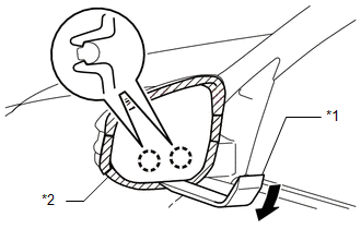
(b) Using a moulding remover, detach the 2 claws of the outer mirror LH as shown in the illustration. Text in Illustration
|
|
|
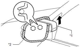
(c) Using a moulding remover, detach the 2 claws of the outer mirror LH as shown in the illustration. Text in Illustration
|
|
|
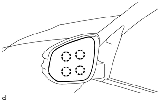
(d) Disconnect the connector and remove the outer mirror LH. |
|
.png)
Inspection
INSPECTION
CAUTION / NOTICE / HINT
HINT:
- Use the same procedure for both the RH and LH sides.
- The procedure listed below is for the LH side.
PROCEDURE
1. INSPECT OUTER MIRROR LH
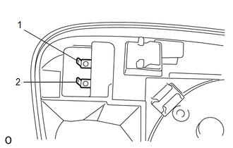
(a) Check the outer mirror heater operation.
|
(1) Measure the resistance according to the value(s) in the table below. Standard Resistance:
If the result is not as specified, replace the outer mirror LH. |
|
Installation
INSTALLATION
CAUTION / NOTICE / HINT
HINT:
- Use the same procedure for both the RH and LH sides.
- The procedure listed below is for the LH side.
PROCEDURE
1. INSTALL OUTER MIRROR LH
(a) Connect the connector.
|
(b) Attach the 4 claws to install the outer mirror LH. |
|
 Outer Rear View Mirror Cover
Components
COMPONENTS
ILLUSTRATION
Removal
REMOVAL
CAUTION / NOTICE / HINT
HINT:
Use the same procedure for both the RH and LH sides.
The procedure listed below is for the LH ...
 Power Mirror Control System
Precaution
PRECAUTION
1. IGNITION SWITCH EXPRESSION
HINT:
The type of ignition switch used on this model differs according to the specifications
of the vehicle. The expressions listed in the t ...
Other materials about Toyota 4Runner:
ACC Signal Circuit
DESCRIPTION
This circuit detects the ignition switch ACC or off condition, and sends it to
the main body ECU.
WIRING DIAGRAM
CAUTION / NOTICE / HINT
NOTICE:
Inspect the fuses for circuits related to this system before performing the following
inspec ...
Touch Panel Switch does not Function
PROCEDURE
1.
CHECK MULTI-DISPLAY
(a) Check if there is any foreign matter caught between the display and exterior
frame of the multi-display.
OK:
No foreign matter is caught between the display and exterior frame of the m ...

0.0086