Toyota 4Runner: No Communication in Immobiliser System (B2796,B2798)
DESCRIPTION
- DTC B2796 is stored when a key is inserted into the ignition key cylinder but no communication occurs between the key and transponder key ECU assembly.
- DTC B2798 is stored when a key is inserted into the ignition key cylinder but a communication error occurs between the key and transponder key ECU assembly.
|
DTC Code |
DTC Detection Condition |
Trouble Area |
|---|---|---|
|
B2796 |
The key code cannot be transmitted. |
|
|
B2798 |
Key code identification cannot be completed within the specified time. |
Key |
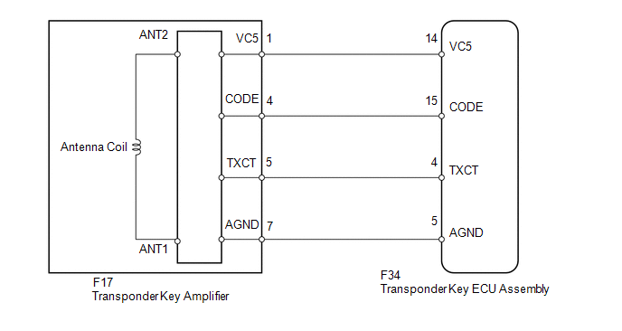
WIRING DIAGRAM
CAUTION / NOTICE / HINT
NOTICE:
When the transponder key ECU assembly is replaced, refer to Registration (See
page .gif) ).
).
PROCEDURE
|
1. |
CLEAR DTC |
(a) Clear the DTCs (See page ).
|
.gif)
|
2. |
CHECK FOR DTC |
(a) Check for DTCs (See page ).
OK:
DTC B2796 or B2798 is not output.
| OK | .gif) |
USE SIMULATION METHOD TO CHECK |
|
|
3. |
READ VALUE USING TECHSTREAM (ENGINE IMMOBILISER SYSTEM) |
(a) Use the Data List to check if the engine immobiliser system is functioning
properly (See page ).
Immobiliser
|
Tester Display |
Measurement Item/Range |
Normal Condition |
Diagnostic Note |
|---|---|---|---|
|
Immobiliser |
Immobiliser system status / Set or Unset |
Set: No key in ignition key cylinder Unset: Key inserted in ignition key cylinder |
- |
OK:
Set (the key is not inserted in the ignition key cylinder) and Unset (the key is inserted in the ignition key cylinder) appear on the screen according to the key insertion condition.
| OK | |
REPLACE TRANSPONDER KEY ECU ASSEMBLY |
|
|
4. |
CHECK WHETHER ENGINE STARTS WITH OTHER KEYS |
(a) Check if the engine starts with an already registered vehicle key.
OK:
Engine starts.
| OK | |
REREGISTER KEY CODE OR REPLACE KEY THAT CANNOT START ENGINE |
|
|
5. |
CHECK HARNESS AND CONNECTOR (TRANSPONDER KEY ECU - TRANSPONDER KEY AMPLIFIER) |
(a) Disconnect the F34 ECU connector.
(b) Disconnect the F17 amplifier connector.
(c) Measure the resistance according to the value(s) in the table below.
Standard Resistance:
|
Tester Connection |
Condition |
Specified Condition |
|---|---|---|
|
F34-14 (VC5) - F17-1 (VC5) |
Always |
Below 1 Ω |
|
F34-15 (CODE) - F17-4 (CODE) |
||
|
F34-4 (TXCT) - F17-5 (TXCT) |
||
|
F34-5 (AGND) - F17-7 (AGND) |
||
|
F34-14 (VC5) or F17-1 (VC5) - Body ground |
Always |
10 kΩ or higher |
|
F34-15 (CODE) or F17-4 (CODE) - Body ground |
||
|
F34-4 (TXCT) or F17-5 (TXCT) - Body ground |
||
|
F34-5 (AGND) or F17-7 (AGND) - Body ground |
| NG | |
REPAIR OR REPLACE HARNESS OR CONNECTOR |
|
|
6. |
REPLACE TRANSPONDER KEY AMPLIFIER |
(a) Temporarily replace the transponder key amplifier with a new or normally
functioning one (See page ).
|
|
7. |
CHECK WHETHER ENGINE STARTS |
(a) Check that the engine starts normally.
OK:
Engine starts normally.
| OK | |
END (TRANSPONDER KEY AMPLIFIER IS DEFECTIVE) |
| NG | |
REPLACE TRANSPONDER KEY ECU ASSEMBLY |
 Theft Deterrent System Presence Detection (B279C)
DESCRIPTION
If an ECM that is incompatible with the engine immobiliser system is installed,
the ECM stores this DTC.
DTC Code
DTC Detection Condition
Trouble Area
...
 Security Indicator Light Circuit
DESCRIPTION
When the engine immobiliser system is set, the security indicator light
blinks continuously, but does not illuminate if the engine immobiliser system
is not set.
WIR ...
Other materials about Toyota 4Runner:
Transmission Control Cable
Components
COMPONENTS
ILLUSTRATION
Removal
REMOVAL
PROCEDURE
1. REMOVE CONSOLE BOX ASSEMBLY
(a) Remove the console box assembly (See page
).
2. REMOVE TRANSMISSION CONTROL CABLE ASSEMBLY
(a) Move the shift lever to N.
(b) Disconne ...
Installation
INSTALLATION
CAUTION / NOTICE / HINT
CAUTION:
Wear protective gloves. Sharp areas on the parts may injure your hands.
HINT:
A bolt without a torque specification is shown in the standard bolt chart (See
page ).
PROCEDURE
1. INSTALL NO. 1 SEAT 3 POINT ...

0.0271