Toyota 4Runner: Installation
INSTALLATION
CAUTION / NOTICE / HINT
CAUTION:
Wear protective gloves. Sharp areas on the parts may injure your hands.
HINT:
A bolt without a torque specification is shown in the standard bolt chart (See
page .gif) ).
).
PROCEDURE
1. INSTALL NO. 1 SEAT 3 POINT TYPE BELT ASSEMBLY LH
NOTICE:
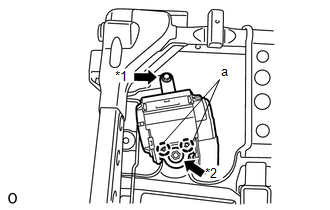
When installing the retractor, make sure the claws of the vehicle (labeled "a" in the illustration) only contact the installation areas of the retractor.
(a) Align the claws with the seat belt positioning holes and install the retractor of the seat belt with the nut and bolt as shown in the illustration.
HINT:
First install the bolt, and then install the nut.
Torque:
for bolt :
7.5 N·m {76 kgf·cm, 66 in·lbf}
for nut :
42 N·m {428 kgf·cm, 31 ft·lbf}
Text in Illustration|
*1 |
Bolt |
|
*2 |
Nut |
2. INSTALL REAR SEAT SHOULDER BELT GUIDE
3. INSTALL REAR SEATBACK EDGE PROTECTOR
4. INSTALL SEATBACK COVER WITH PAD
5. INSTALL REAR NO. 1 SEAT HEADREST SUPPORT ASSEMBLY
6. INSTALL REAR SEATBACK BOARD CARPET ASSEMBLY LH
7. INSTALL REAR SEATBACK COVER
8. INSTALL REAR SEAT SHOULDER BELT COVER
9. INSTALL SEAT BELT ANCHOR COVER CAP
10. INSTALL REAR SEAT LOCK CONTROL LEVER SUB-ASSEMBLY LH
11. INSTALL RECLINING ADJUSTER KNOB CAP LH
12. INSTALL REAR NO. 1 SEAT INNER BELT ASSEMBLY LH
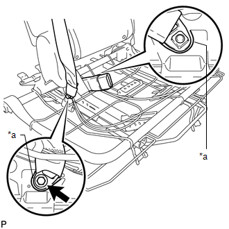
(a) Install the inner belt and connect the 3 point type belt anchor with the bolt.
Torque:
42 N·m {428 kgf·cm, 31 ft·lbf}
NOTICE:
Do not allow the anchor part of the anchor plate sub-assembly to overlap the protruding parts of the seatback frame.
Text in Illustration|
*1 |
Protruding Part |
13. INSTALL CENTER SEATBACK ASSEMBLY
14. INSTALL SEAT CUSHION COVER WITH PAD
15. INSTALL REAR SEATBACK LOCK STRIKER COVER LH
16. INSTALL REAR SEAT CUSHION MOULDING LH
17. INSTALL CENTER SEAT HINGE COVER RH
18. INSTALL RECLINING ADJUSTER RELEASE HANDLE LH
19. INSTALL REAR SEAT UPPER RECLINING COVER LH
20. INSTALL REAR NO. 1 SEAT ASSEMBLY LH
(a) Install the rear No. 1 seat assembly LH (See page
).
 Removal
REMOVAL
CAUTION / NOTICE / HINT
CAUTION:
Wear protective gloves. Sharp areas on the parts may injure your hands.
PROCEDURE
1. REMOVE REAR NO. 1 SEAT ASSEMBLY LH
(a) Remove the rear No. 1 seat as ...
 Rear No. 1 Seat Inner Belt Assembly(for 60/40 Split Double-folding Seat Type
Lh Side)
Rear No. 1 Seat Inner Belt Assembly(for 60/40 Split Double-folding Seat Type
Lh Side)
Components
COMPONENTS
ILLUSTRATION
Installation
INSTALLATION
PROCEDURE
1. INSTALL REAR NO. 1 SEAT INNER BELT ASSEMBLY LH
(a) Install the inner belt with the bolt.
Torque:
42 N·m {428 ...
Other materials about Toyota 4Runner:
Dtc Check / Clear
DTC CHECK / CLEAR
1. CHECK/CLEAR DTC (USING TECHSTREAM)
(a) Check DTC:
(1) Connect the Techstream to the DLC3.
(2) Turn the ignition switch to ON.
(3) Turn the Techstream on.
(4) Enter the following menus: Chassis / KDSS / Trouble Codes.
(5) Read DTCs b ...
Precaution
PRECAUTION
1. IGNITION SWITCH EXPRESSION
HINT:
The type of ignition switch used on this model differs depending on the specifications
of the vehicle. The expressions listed in the table below are used in this section.
Expression
Ign ...

0.0168