Toyota 4Runner: No Response from ID BOX (B2789)
DESCRIPTION
This DTC is stored when LIN communication between the certification ECU and ID code box stops for 10 seconds or more.
|
DTC Code |
DTC Detection Condition |
Trouble Area |
|---|---|---|
|
B2789 |
No communication between the certification ECU and ID code box for 10 seconds or more. |
|
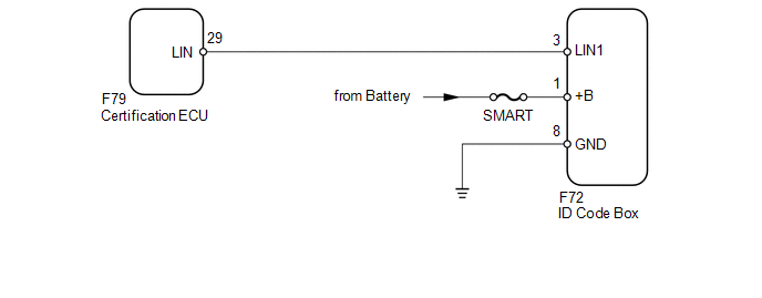
WIRING DIAGRAM
CAUTION / NOTICE / HINT
NOTICE:
- When using the Techstream with the ignition switch off to troubleshoot:
Connect the Techstream to the vehicle and turn a courtesy light switch on and off at 1.5 second intervals until communication between the Techstream and vehicle begins.
- Inspect the fuses and bulbs for circuits related to this system before performing the following inspection procedure.
HINT:
When communication between the ID code box and certification ECU stops, DTC B2785 is also stored.
PROCEDURE
|
1. |
CLEAR DTC |
(a) Clear the DTCs (See page .gif) ).
).
|
.gif)
|
2. |
CHECK FOR DTC |
(a) Check for DTCs (See page ).
OK:
DTC B2789 is not output.
| OK | .gif) |
USE SIMULATION METHOD TO CHECK |
|
|
3. |
CHECK HARNESS AND CONNECTOR (CERTIFICATION ECU - ID CODE BOX) |
(a) Disconnect the F79 certification ECU connector.
(b) Disconnect the F72 ID code box connector.
(c) Measure the resistance according to the value(s) in the table below.
Standard Resistance:
|
Tester Connection |
Condition |
Specified Condition |
|---|---|---|
|
F79-29 (LIN) - F72-3 (LIN1) |
Always |
Below 1 Ω |
|
F79-29 (LIN) or F72-3 (LIN1) - Body ground |
Always |
10 kΩ or higher |
| NG | |
REPAIR OR REPLACE HARNESS OR CONNECTOR |
|
|
4. |
CHECK HARNESS AND CONNECTOR (ID CODE BOX - BATTERY AND BODY GROUND) |
|
(a) Disconnect the F72 ID code box connector. |
|
(b) Measure the resistance and voltage according to the value(s) in the table below.
Standard Resistance:
|
Tester Connection |
Condition |
Specified Condition |
|---|---|---|
|
F72-8 (GND) - Body ground |
Always |
Below 1 Ω |
(c) Measure the voltage according to the value(s) in the table below.
Standard Voltage:
|
Tester Connection |
Condition |
Specified Condition |
|---|---|---|
|
F72-1 (+B) - Body ground |
Always |
11 to 14 V |
|
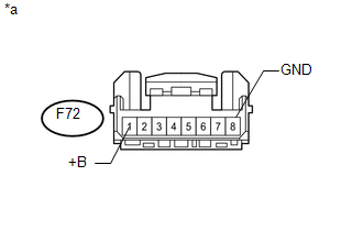
*a |
Front view of wire harness connector (to ID Code Box) |
| NG | |
REPAIR OR REPLACE HARNESS OR CONNECTOR |
|
|
5. |
REPLACE ID CODE BOX |
(a) Temporarily replace the ID code box with a new one (See page
).
|
|
6. |
CLEAR DTC |
(a) Clear the DTCs (See page ).
|
|
7. |
CHECK FOR DTC |
(a) Check for DTCs (See page ).
OK:
DTC B2789 is not output.
| OK | |
END (ID CODE BOX IS DEFECTIVE) |
| NG | |
REPLACE CERTIFICATION ECU |
 Diagnostic Trouble Code Chart
DIAGNOSTIC TROUBLE CODE CHART
Main Body ECU (Multiplex Network Body ECU)
DTC Code
Detection Item
See page
B1206
P/W Master Switch Communi ...
 Lost Communication with Combination Meter (B2661,B2662)
DESCRIPTION
This DTC is stored when LIN communication between the drive monitor switch and
combination meter assembly stops 10 seconds or more.
DTC Code
DTC Detection Conditi ...
Other materials about Toyota 4Runner:
Air Conditioning Compressor Magnetic Clutch Circuit
DESCRIPTION
When the air conditioning amplifier assembly is turned on, a magnet clutch assembly
ON signal is sent from the MGC terminal of the air conditioning amplifier assembly.
Then, the A/C COMP relay turns on to operate the magnet clutch assembly.
W ...
Installation
INSTALLATION
PROCEDURE
1. INSTALL FRONT DIFFERENTIAL CARRIER ASSEMBLY
(a) Install the front No. 3 differential support with the 2 bolts.
Torque:
108 N·m {1101 kgf·cm, 80 ft·lbf}
(b) Install the front No. 2 differential support with the 2 bolts.
Torq ...

0.0289