Toyota 4Runner: No Response from Steering Lock ECU (B2786)
DESCRIPTION
This DTC is stored when LIN communication between the certification ECU and steering lock actuator assembly (steering lock ECU) stops for 10 seconds or more.
|
DTC Code |
DTC Detection Condition |
Trouble Area |
|---|---|---|
|
B2786 |
LIN communication between the certification ECU and steering lock ECU stops for 10 seconds or more. |
|
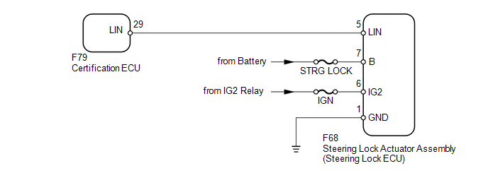
WIRING DIAGRAM
CAUTION / NOTICE / HINT
NOTICE:
- When using the Techstream with the ignition switch off to troubleshoot:
Connect the Techstream to the vehicle and turn a courtesy light switch on and off at 1.5 second intervals until communication between the Techstream and vehicle begins.
- Inspect the fuses and bulbs for circuits related to this system before performing the following inspection procedure.
HINT:
When communication between the steering lock ECU and certification ECU stops, DTC B2785 is also stored.
PROCEDURE
|
1. |
CLEAR DTC |
(a) Clear the DTCs (See page .gif) ).
).
|
.gif)
|
2. |
CHECK FOR DTC |
(a) Check for DTCs (See page ).
OK:
DTC B2786 is not output.
| OK | .gif) |
USE SIMULATION METHOD TO CHECK |
|
|
3. |
CHECK HARNESS AND CONNECTOR (CERTIFICATION ECU - STEERING LOCK ECU) |
(a) Disconnect the F79 certification ECU connector.
(b) Disconnect the F68 steering lock actuator assembly (steering lock ECU) connector.
(c) Measure the resistance according to the value(s) in the table below.
Standard Resistance:
|
Tester Connection |
Condition |
Specified Condition |
|---|---|---|
|
F79-29 (LIN) - F68-5 (LIN) |
Always |
Below 1 Ω |
|
F79-29 (LIN) or F68-5 (LIN) - Body ground |
Always |
10 kΩ or higher |
| NG | |
REPAIR OR REPLACE HARNESS OR CONNECTOR |
|
|
4. |
CHECK HARNESS AND CONNECTOR (STEERING LOCK ECU - BATTERY AND BODY GROUND) |
|
(a) Disconnect the F68 steering lock actuator assembly (steering lock ECU) connector. |
|
(b) Measure the resistance according to the value(s) in the table below.
Standard Resistance:
|
Tester Connection |
Condition |
Specified Condition |
|---|---|---|
|
F68-1 (GND) - Body ground |
Always |
Below 1 Ω |
(c) Measure the voltage according to the value(s) in the table below.
Standard Voltage:
|
Tester Connection |
Switch Condition |
Specified Condition |
|---|---|---|
|
F68-6 (IG2) - Body ground |
Ignition switch ON |
11 to 14 V |
|
F68-7 (B) - Body ground |
Always |
11 to 14 V |
|
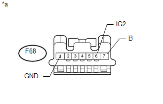
*a |
Front view of wire harness connector (to Steering Lock Actuator Assembly [Steering Lock ECU]) |
| NG | |
REPAIR OR REPLACE HARNESS OR CONNECTOR |
|
|
5. |
REPLACE STEERING LOCK ACTUATOR ASSEMBLY (STEERING LOCK ECU) |
(a) Temporarily replace the steering lock actuator (steering lock ECU) assembly
with a new one (See page ).
|
|
6. |
CLEAR DTC |
(a) Clear the DTCs (See page ).
|
|
7. |
CHECK FOR DTC |
(a) Check for DTCs (See page ).
OK:
DTC B2786 is not output.
| OK | |
END (STEERING LOCK ECU IS DEFECTIVE) |
| NG | |
REPLACE CERTIFICATION ECU |
 Data List / Active Test
DATA LIST / ACTIVE TEST
1. READ DATA LIST
HINT:
Using the Techstream to read the Data List allows the values or states of switches,
sensors, actuators and other items to be read without removing ...
 Diagnostic Trouble Code Chart
DIAGNOSTIC TROUBLE CODE CHART
Main Body ECU (Multiplex Network Body ECU)
DTC Code
Detection Item
See page
B1206
P/W Master Switch Communi ...
Other materials about Toyota 4Runner:
Theft Deterrent System Presence Detection (B279C)
DESCRIPTION
If an ECM that is incompatible with the engine immobiliser system is installed,
the ECM stores this DTC.
DTC Code
DTC Detection Condition
Trouble Area
B279C
An ECM for vehicles withou ...
Portable Player cannot be Operated Using In-vehicle Device or Track Information
is not Displayed on In-vehicle Device
PROCEDURE
1.
CHECK USING ANOTHER "Bluetooth" AUDIO COMPATIBLE VEHICLE OF SAME MODEL
(a) Check if track information is displayed normally on another "Bluetooth" audio
compatible vehicle of the same model.
...

0.0073