Toyota 4Runner: On-vehicle Inspection
ON-VEHICLE INSPECTION
PROCEDURE
1. CHECK AUTOMATIC LIGHT CONTROL SENSOR
|
(a) Measure the voltage according to the value(s) in the table below. Standard Voltage:
|
|
(b) Measure the resistance according to the value(s) in the table below.
Standard Resistance:
|
Tester Connection |
Switch Condition |
Specified Condition |
|---|---|---|
|
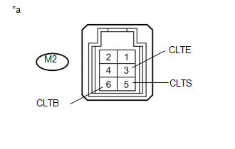
G2-3 (CLTE) - Body ground |
Always |
Below 1 Ω |
(c) Reconnect the G2 sensor connector.
|
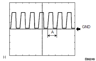
(d) Check the waveform of the G2 sensor connector. Waveform:
HINT: If the ambient light becomes brighter, width A becomes narrower. If the result is not as specified, there may be a malfunction in the automatic light control sensor. Text in Illustration
|
|
 Components
COMPONENTS
ILLUSTRATION
...
 Removal
REMOVAL
PROCEDURE
1. REMOVE INSTRUMENT PANEL SUB-ASSEMBLY
(a) Remove the instrument panel sub-assembly (See page
).
2. REMOVE NO. 1 HEATER TO REGISTER DUCT
3. REMOVE NO. 2 HEATER TO REGISTER ...
Other materials about Toyota 4Runner:
Problem Symptoms Table
PROBLEM SYMPTOMS TABLE
NOTICE:
After replacing the stereo component tuner assembly of vehicles subscribed to
pay-type satellite radio broadcasts, XM radio ID registration is necessary (w/ SDARS
System).
HINT:
Use the table below to help determi ...
Reassembly
REASSEMBLY
CAUTION / NOTICE / HINT
HINT:
Use the same procedure for both the RH and LH sides.
The procedure listed below is for the LH side.
PROCEDURE
1. INSTALL FOG LIGHT BULB
(a) Turn the bulb in the direction indicated by ...

0.0183