
Toyota 4Runner: Components
COMPONENTS
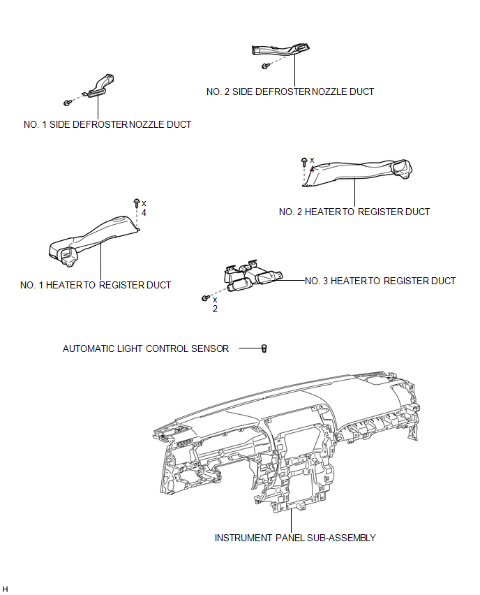
ILLUSTRATION

 On-vehicle Inspection
ON-VEHICLE INSPECTION
PROCEDURE
1. CHECK AUTOMATIC LIGHT CONTROL SENSOR
(a) Measure the voltage according to the value(s) in the table below.
Standard Voltage:
Te ...
Other materials about Toyota 4Runner:
On-vehicle Inspection
ON-VEHICLE INSPECTION
PROCEDURE
1. INSPECT REFRIGERANT PRESSURE WITH MANIFOLD GAUGE SET
(a) This method uses a manifold gauge set to locate problem areas. Read the manifold
gauge pressure when these conditions are established.
Test conditions:
Te ...
Removal
REMOVAL
PROCEDURE
1. DISCONNECT CABLE FROM NEGATIVE BATTERY TERMINAL
CAUTION:
Wait at least 90 seconds after disconnecting the cable from the negative (-)
battery terminal to disable the SRS system.
NOTICE:
When disconnecting the cable, some systems ne ...
© 2016-2026 | www.to4runner.net

0.0078
0.0078