Toyota 4Runner: On-vehicle Inspection
ON-VEHICLE INSPECTION
PROCEDURE
1. INSPECT VOLTAGE INVERTER ASSEMBLY
HINT:
Remove interior parts so that the voltage inverter can be seen.
|
(a) Disconnect the voltage inverter connector. |
|
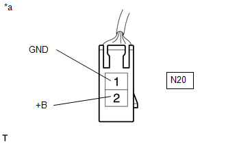
(b) Measure the voltage according to the value(s) in the table below.
Standard Voltage:
|
Tester Connection |
Switch Condition |
Specified Condition |
|---|---|---|
|
N20-1 (GND) - N20-2 (+B) |
Engine switch on (IG) |
11 to 14 V |
|
N20-1 (GND) - Body ground |
Always |
Below 1 V |
If the result is not as specified, repair or replace the harness or connector.
Text in Illustration|
*a |
Front view of wire harness connector (to Voltage Inverter Assembly) |
|
(c) Reconnect the voltage inverter connector. |
|
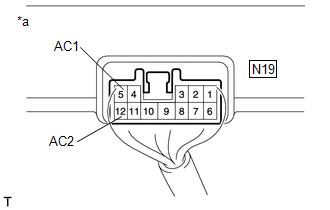
(d) Measure the voltage according to the value(s) in the table below.
Standard Voltage:
|
Tester Connection |
Switch Condition |
Specified Condition |
|---|---|---|
|
N19-5 (AC1) - N19-11 (AC2) |
Engine switch on (IG), main switch on |
AC 120 V |
If the result is not as specified, replace the voltage inverter assembly.
Text in Illustration|
*a |
Component with harness connected (Voltage Inverter Assembly) |
 Components
COMPONENTS
ILLUSTRATION
ILLUSTRATION
ILLUSTRATION
ILLUSTRATION
ILLUSTRATION
...
 Removal
REMOVAL
PROCEDURE
1. REMOVE REAR NO. 1 FLOOR STEP COVER (w/ Rear No. 2 Seat)
2. REMOVE QUARTER SCUFF PLATE RH (w/ Rear No. 2 Seat)
3. REMOVE REAR DOOR SCUFF PLATE RH
4. REMOVE REAR DOOR ...
Other materials about Toyota 4Runner:
Removal
REMOVAL
CAUTION / NOTICE / HINT
HINT:
Use the same procedure for the RH and LH sides.
The procedure listed below is for the LH side.
PROCEDURE
1. DISCONNECT CABLE FROM NEGATIVE BATTERY TERMINAL
CAUTION:
Wait at least 90 seconds after d ...
Diagnostic Trouble Code Chart
DIAGNOSTIC TROUBLE CODE CHART
Rear View Monitor System
DTC No.
Detection Item
Link
C1622
Back Camera Disconnected
...

0.0066