Toyota 4Runner: Steering Angle Sensor
Components
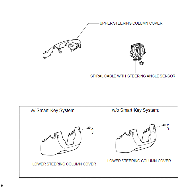
COMPONENTS
ILLUSTRATION
Removal
REMOVAL
PROCEDURE
1. PLACE FRONT WHEELS FACING STRAIGHT AHEAD
2. DISCONNECT CABLE FROM NEGATIVE BATTERY TERMINAL
CAUTION:
Wait at least 90 seconds after disconnecting the cable from the negative (-) battery terminal to disable the SRS system.
NOTICE:
When disconnecting the cable, some systems need to be initialized after the cable
is reconnected (See page .gif) ).
).
3. REMOVE STEERING WHEEL ASSEMBLY
(a) Remove the steering wheel assembly (See page
).
4. REMOVE LOWER STEERING COLUMN COVER
5. REMOVE UPPER STEERING COLUMN COVER
6. REMOVE SPIRAL CABLE WITH STEERING ANGLE SENSOR
(a) Remove the spiral cable with steering angle sensor (See page
).
NOTICE:
- Do not replace the spiral cable with the battery connected and the ignition switch ON.
- Do not rotate the spiral cable with the battery connected and the ignition switch ON.
- Make sure that the steering wheel is installed and aligned straight when inspecting the steering angle sensor.
- Do not remove the steering angle sensor from the spiral cable.
Installation
INSTALLATION
PROCEDURE
1. INSTALL SPIRAL CABLE WITH STEERING ANGLE SENSOR
(a) Install the spiral cable with steering angle sensor (See page
.gif) ).
).
NOTICE:
- Do not replace the spiral cable with the battery connected and the ignition switch ON.
- Do not rotate the spiral cable with the battery connected and the ignition switch ON.
- Make sure that the steering wheel is installed and aligned straight when inspecting the steering angle sensor.
- Do not remove the steering angle sensor from the spiral cable.
2. INSTALL UPPER STEERING COLUMN COVER
3. INSTALL LOWER STEERING COLUMN COVER
4. ADJUST SPIRAL CABLE
5. INSTALL STEERING WHEEL ASSEMBLY
(a) Install the steering wheel assembly (See page
).
6. CONNECT CABLE TO NEGATIVE BATTERY TERMINAL
NOTICE:
When disconnecting the cable, some systems need to be initialized after the cable
is reconnected (See page ).
7. CHECK SRS WARNING LIGHT
(a) Check the SRS warning light (See page ).
 Relay
Relay
On-vehicle Inspection
ON-VEHICLE INSPECTION
PROCEDURE
1. CHECK STOP LIGHT CONTROL RELAY
(a) Remove the stop light control relay from the engine room relay block.
(b) Measure the resi ...
 Traction Off Switch
Components
COMPONENTS
ILLUSTRATION
Removal
REMOVAL
PROCEDURE
1. REMOVE DRIVE MONITOR SWITCH
2. REMOVE MAP LIGHT ASSEMBLY
(a) Remove the screws.
...
Other materials about Toyota 4Runner:
Engine Coolant Temperature Receiver Gauge Malfunction
DESCRIPTION
In this circuit, the meter CPU receives engine coolant temperature signals from
the ECM using the CAN communication system. The meter CPU displays the engine coolant
temperature, which is calculated based on the data received from the ECM.
WI ...
Installation
INSTALLATION
CAUTION / NOTICE / HINT
HINT:
Use the same procedure for the RH and LH sides.
The procedure listed below is for the LH side.
PROCEDURE
1. INSTALL FRONT AXLE HUB SUB-ASSEMBLY LH
(a) Apply MP grease to a new O-ring.
(b) Inst ...

0.0243